Personal and area monitors, Specifications for outdoor models, Alarm operation – Atec Narda-8800 Series User Manual
Page 4: J101 wiring diagram, T.o.c
Personal and Area Monitors
///////////
435 MORELAND ROAD HAUPPAUGE, NY 11788
USA TEL: 516 231-1700 INTL TEL: (1) 516 231-1390 FAX (1) 516 231-1711
E-MAIL: [email protected] www.nardaeast.l-3com.com
SPECIFICATIONS FOR OUTDOOR MODELS
MODEL No.
8810B-WP
8815B-WP
8820B-WP
Frequency Range
2 to 30 MHz
10 to 500 MHz
0.5 to 18 GHz
Frequency Sensitivity
±
1.5 dB
±
2.0 dB
±
3.0 dB
=
Alarm Threshold
10% of Standard
>
0.1 mW/cm
1.0 mW/cm
Overload
CW
Peak
60 mW/cm
60 W/cm
300 mW/cm
100 W/cm
3 dB Intercept Angle
>180
°
>180
°
>180
°
?
Temperature
Operating
Non-operating
-20
°
C to +55
°
C
@
-40
°
C to + 75
°
C
Power Requirements
External Supply
8.5-12.5 Vdc, 5 ma (max)
Enclosure Rating
NEMA 4X
B
Weight (approx)
69 oz. (2.0 kg)
66 oz. (1.9 kg)
Calibration Frequencies
C
2, 3, 10 and 30 MHz
10, 30, 100, 300,
400 and 500 MHz
8.2 GHz
Accessories Supplied
Operation Manual, J101 Mating Connector
Notes:
=
Includes enclosure effects. The threshold can be factory set to provide optimum performance over a specific band of interest.
>
The alarm threshold is proportionate to IEEE C95.1-1991 Standard and varies over the 2 to 30 MHz band. The threshold is 0.9% of
the H field Maximum Permissable Exposure (MPE) from 3 to 30 MHz and equal to 10% of the E field MPE from 2 to 30 MHz.
?
The 3 dB intercept angle is >180
°
with the E field tangential to the mounting plane and >165
°
with the E field perpendicular to the
mounting plane.
@
The SMARTS circuitry will operate from -20
°
C to +65
°
C. Extensive thermal analysis indicates that, under worst-case conditions
(no wind, no shade), the temperature inside the weatherproof enclosure will be a maximum of 10
°
C higher than the ambient air
temperature. Therefore, the maximum ambient air temperature is 55
°
C.
A
The fail-safe battery has a rated life of 5 to 10 years. It is recommended that it be checked annually during calibration and replaced
every three years.
B
This is the equivalent of IEC Publication 529, Type IP66 or CSA Standard C22.2, No. 94.
C
Other calibration frequencies available for narrow band applications. Contact the factory.
ALARM OPERATION
Condition
J101 Output
Normal Operation
Low
Test Circuit Opened
High
Alarm
High
Sensor Failure
High
Enable Circuit Closed
Low
External Power Failure
High
Note:
The STATUS signal available at J101 provides >2.4 VDC
into a 24 k
Ω
load when High. The voltage drops to
<0.8 VDC when Low. Maximum sink current is 3 ma.
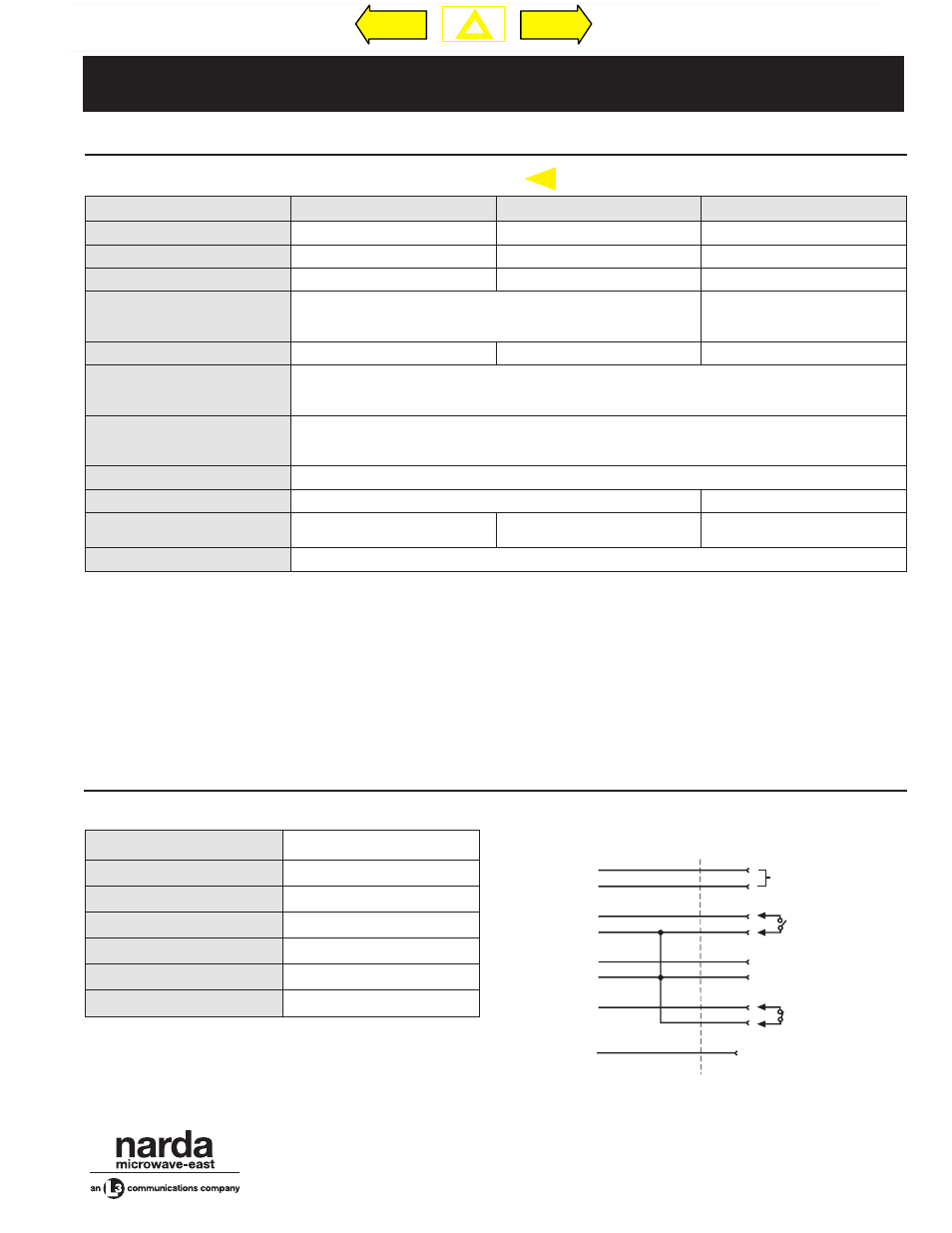
J101 WIRING DIAGRAM
A
K
C
H
E
B
D
F
G, H, J, L, N, P
(FLOATING)
**N.O.
TEST
*N.C.
J101
* MUST BE CLOSED FOR PROPER OPERATION
** MUST BE OPEN FOR PROPER OPERATION
+10V
RET
ENABLE
STATUS
GND
ENABLE (GND)
STATUS (GND)
TEST
SPARE
N
EW
$'
Previous
Next
T.O.C.