Atec Chroma-63800 Series User Manual
Page 5
Model
63800 Series
All specifications are subject to change without notice.
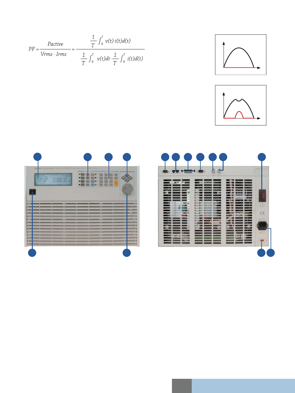
1. LCD display
2. Function keypad :
To select load mode, control mode, and system
config setting
3. Numeric keypad :
For data setting
4. Cursor key :
For setting and editing
5. Power switch
6. Rotary knob :
For rapid control of active parameter
7. TTL I/O :
For system input/output control signal
8. System bus :
For master/slave control system data communication
9. GPIB connector
10. RS-232 connector
11. Voltage monitor output :
Analog output proportional to voltage waveform
12. Current monitor output :
Analog output proportional to the current waveform
13. Load terminal & Voltage sense terminal
14. AC input connector
15. AC input voltage switch
Panel Overview
1
2
3
4
5
6
7
15
8
9
14
13
12
11
10
Ordering Information
63802 : Programmable AC Electronic Load 1800W/18A/350V
63803 : Programmable AC Electronic Load 3600W/36A/350V
63804 : Programmable AC Electronic Load 4500W/45A/350V
Auto Power Factor Correction
Allowing user to set the power factor is one of the major features to the 63800. The power factor is defined as :
Since PF is a function of real time voltage and current, traditional AC load designs assumes the voltage
waveform to be sinusoidal all the time, as seen Figure 11. This is not realistic because the voltage
waveform may be distorted after the load is applied shown in Figure 12, if the control of power factor
is base on the belief of sinusoidal voltage waveform, it will result in a lower power factor than the user
programmed thus overstressing the UUT.
Chroma's 63800 AC loads monitor the power factor reading constantly and uses this data to dynamically
adjust the loading waveform. As a result, the power factor setting is precise without overstressing the
UUT.
Figure 13
Figure 14