Atec Chroma-63800 Series User Manual
Page 3
Rectified AC Load Modes
The 63800 AC/DC Electronic Load provides unique capability to simulate
non-linear rectified loads for a wide range of testing applications. There
are three load modes available for rectified load simulations-RLC, CP and
Inrush Current modes.
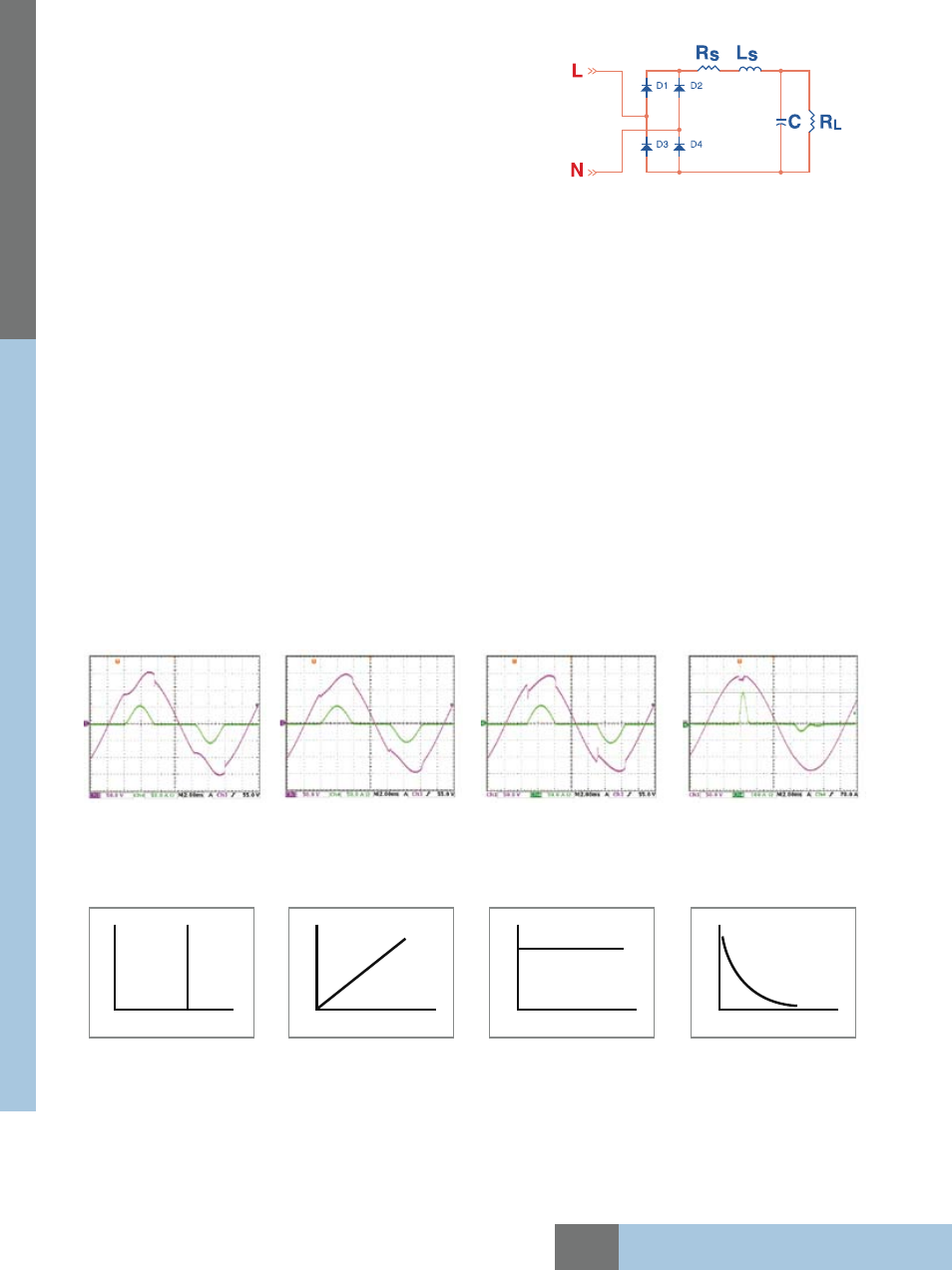
Figure 3: Actual RLC Circuit
Figure 4: Simulated RLC Mode
Figure 5: CC Mode
Figure 6: Inrush Current Mode
DC Load Simulation
Chroma's 63800 DC load simulation includes four load modes : constant current, constant resistance, constant voltage and
constant power as depicted below.
Constant current Constant resistance Constant voltage Constant power
CC, CR, CP mode can be used for regulated voltage power supplies testing. For battery charger, CV mode may help to check its
current regulation.
A special DC Rectified mode is included to simulate the loading behavior of Distributed Inverters. Many inverter designs, although
its input is DC, the input current will show rectified pattern. This unique load mode makes Chroma 63800 load ideal for Fuel Cell, PV
module/array and Battery test because those devices will be loaded by Inverters.
Figure 2 : Typical Rectified Circuit
V
I
V
I
V
I
V
I
Figure 2 shows the typical model of an rectifier input. Under RLC mode, users can set the RLC values to 100% simulate the behavior of
actual UUT. Figure 3 & 4 compares the voltage and loading waveforms between the actual RLC built circuit and the simulated rectified
circuit by using Chroma RLC load mode. The waveform of the 63800 in RLC mode looks almost identical to the waveform of actual
hardware circuit. The waveform obtained under CC mode with same loading crest factor shown in Figure 5 looks far from the waveform
of actual hardware circuit.
In addition, traditional AC loads can only use CR mode to test discontinuous square or quasi-square wave UUTs because CC and CP
are all active loadings and requires a defined frequency. It's very difficult to detect the frequency of a discontinuous square or quasi-
square wave. Since RLC mode of the 63800 load is actually simulating passive loading it doesn't require a defined frequency, therefore
it allows the user to simulate loading in modes other than just CR. Using discrete RLC network may solve the problem too, however
due to component weight, size and limited RLC values this makes it inconvenient for testing. In contrast, Chroma's 63800 RLC mode
provides versatile settings and higher test flexibilities.
For production line testing, most of users may not know their required RLC values but likely know the UUTs power rating and PF
values. In this case, CP mode is ideal for test engineers. Under CP mode, the 63800 built-in algorithm will find the best solution to get
the RLC values automatically according to the power rating and PF value set by the user.
To avoid overstressing the UUT, both the RLC and CP modes will gradually increase the loading current up to the programmed loading
current shown in Figure 4, simulating actual RLC circuit loading as shown in Figure 3. This will alleviate the sudden voltage drop from
constant current loading mode as shown in Figure 5.
For one that wishes to simulate the inrush current, the 63800 provides Inrush Current mode, allowing users to set different inrush
current amplitude and the voltage phase angle where the inrush current started.
PR
O
G
R
A
M
M
A
B
LE
A
C/
D
C
E
LE
CT
R
O
N
IC
L
O
A
D
Model
63800 Series
All specifications are subject to change without notice.