Smartwave – Atec Elgar-SW1750A-SW3500A-SW5250A User Manual
Page 6
6
6
ENVIRONMENTAL DATA
Operating Temperature: 0°C to 45°C (32°F to 113°F)
Storage Temperature: -40°C to 70°C (-40°F to 158°F)
Humidity (Non-condensing): 0 to 85% at 25°C (77°F);
derate to 50% at 40°C (104°F)
Altitude: Operating 10,000 ft, non operating 40,000 ft
SMARTWAVE
TM
(SW)
SPECIFICATIONS CONTINUED AND MODEL NUMBERING
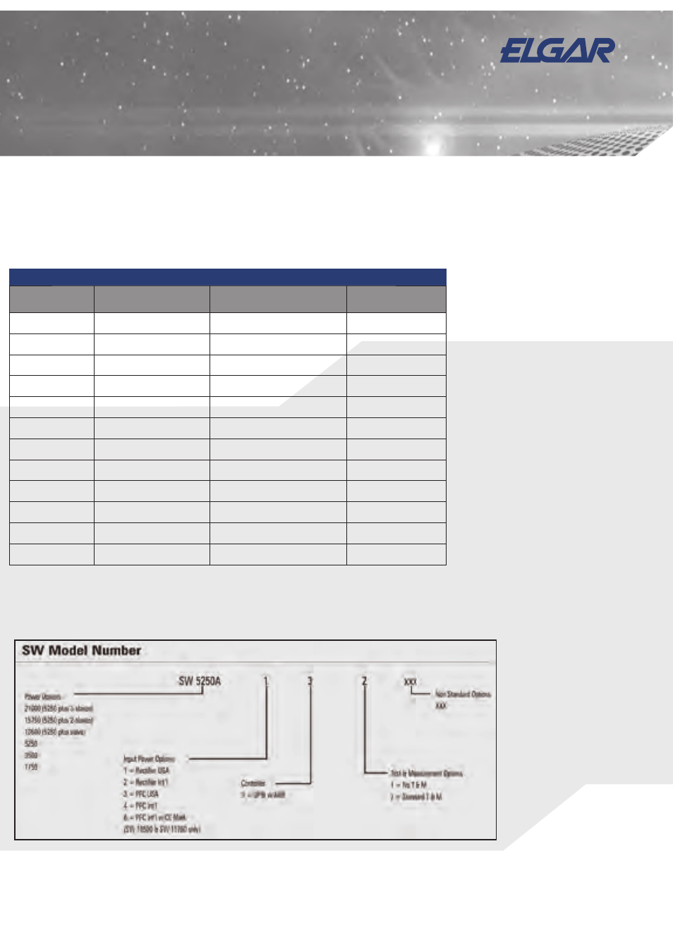
ORDERING INFORMATION
MODEL NUMBER
OUTPUT POWER RATING
AC INPUT
POWER FACTOR
CORRECTION (PFC)
SW 1750A-1
1750 VA
1
187-264 VRMS (L-L), 3-wire
NO
SW 1750A-2
1750 VA
1
342-457 VRMS (L-L), 4-wire
NO
SW 1750A-3
1750 VA
1
187-264 VRMS (L-L), 3-wire
YES
SW 1750A-4
1750 VA
1
342-457 VRMS (L-L), 4-wire
YES
SW 3500A-1
3500 VA
2
187-264 VRMS (L-L), 3-wire
NO
SW 3500A-2
3500 VA
2
342-457 VRMS (L-L), 4-wire
NO
SW 3500A-3
3500 VA
2
187-264 VRMS (L-L), 3-wire
YES
SW 3500A-4
3500 VA
2
342-457 VRMS (L-L), 4-wire
YES
SW 5250A-1
5250 VA
3
187-264 VRMS (L-L), 3-wire
NO
SW 5250A-1
5250 VA
3
342-457 VRMS (L-L), 4-wire
NO
SW 5250A-1
5250 VA
3
187-264 VRMS (L-L), 3-wire
YES
SW 5250A-1
5250 VA
3
342-457 VRMS (L-L), 4-wire
YES
1
1495 VA at 115V or 230V output
2
2990 VA at 115V or 230V output
3
4485 VA at 115V or 230V output
OPTIONS
• Measurement capability
• Input power factor correction to
0.99
• 16A/phase output
• Parallelable for additional power
from 10.5 kVA to 21 kVA
• External waveform creation
software DSP2
• 5V or 26V, 0.25A auxiliary AC
outputs
• Custom cabinets for 10.5, 15.75
& 21 kVA systems
• Interharmonic waveform
generator
• Low speed fan option
OTHER STANDARD FEATURES
• 1ø to 3ø programmable
• IEEE-488.2 interface
• SCPI protocol
• WaveForm trigger output: (1 MΩ Load
Drive)
• BNC outputs for scope viewing of
waveforms (1 MΩ Load Drive)
• SYNC OUT. User programmed for: Cycle
start, all cycles. Segment start, all or
selected segments. For loads ≥ 2 kΩ: V
out ≤ 1V low state; V out ≥ 2.4V high
state
• External Amplitude Modulation
0 to 5 VRMS provides 0 to ≥ 20% output
amplitude modulation
• Clock/lock:
Clock - pulses at programmed frequency.
For loads ≥ 2 kΩ V out: ≤ 1V low state; V
out ≥ 2.4V high state
Lock - locks output to input ‘TTL’ frequency;
signal needs to supply pull down current of
15 mA with voltage drop of ≤ 0.6V; no pull
up needed
• External Drive: Normal amplifi er, 0 to 5
VRMS (DC to 5 kHz) or ±5 VDC input for
zero to full voltage output
• External Gain Control: 0 to ±7.07 VDC
provides zero to full output
• External Input Impedance ≥ 30 kΩ