Main system, Ethernet connector, Vga connector – Atec Dewetron-3010 User Manual
Page 11: Rs-232 interface connector (com1)
13
DE-M0365E • DEWE-3010 • Technical Reference Manual • Printing version 2.0.5 • Oct
ober 18, 2004
5 4 3 2 1
1514131211
10 9 8 7 6
1 2 3 4 5
6 7 8 9
15.7 mm
7.5
mm
Main System
5. Ethernet connector
The DEWE-3010 system supports 10/100 BaseT Ethernet with standard RJ45 connector.
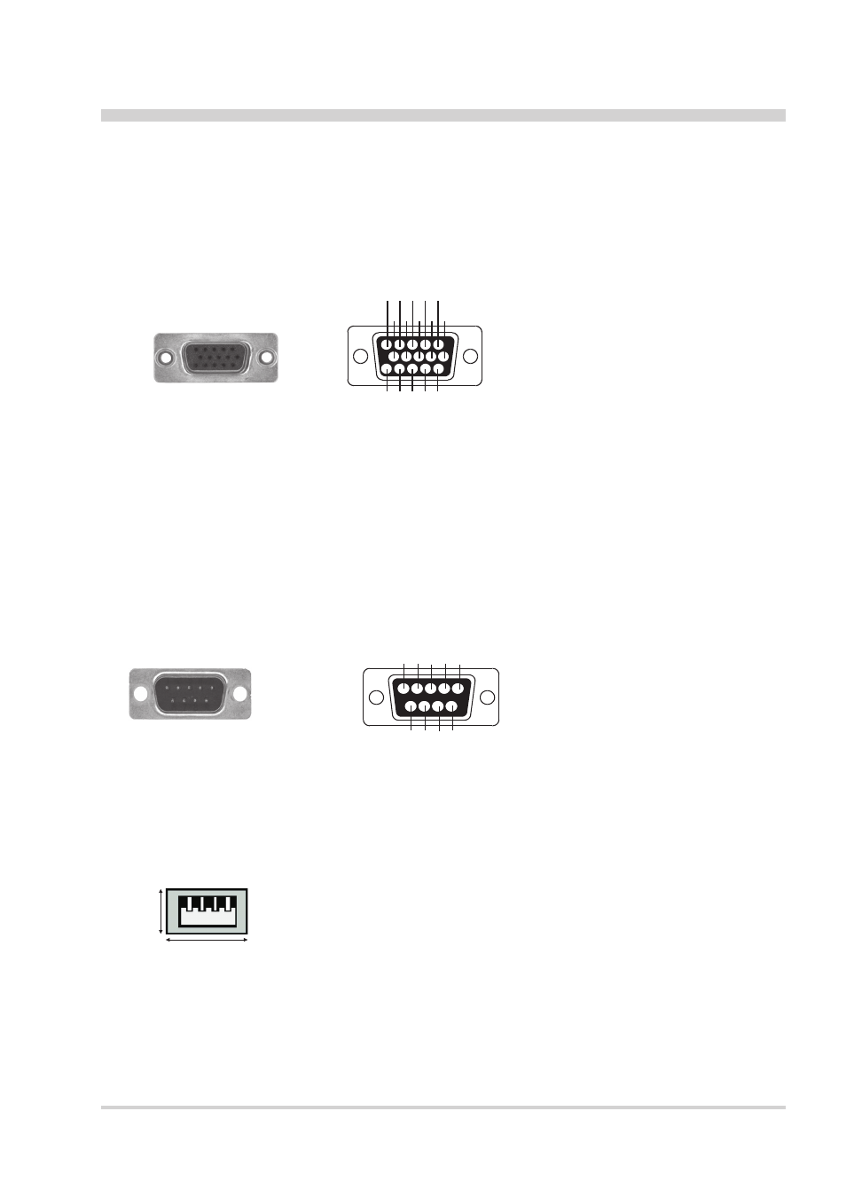
6. VGA connector
The VGA connector offers the possibility to connect an external CRT or other standard VGA displays to the
system.
15-pin mini SUB-D connector
Schematic
Pin assignment
1: Red video
2: Green video / Sync on green
3: Blue video
4: -
5: -
6: Red video ground
7: Green video ground
8: Blue video ground
9: -
10: Ground
11: Ground
12: Data line
13: H-Sync / HV-Sync
14: V-Sync
15: Clock line
7. RS-232 interface connector (COM1)
The RS-232 interface connector (male) is located on the right side of the DEWE-3010. It is configured as
standard RS-232 interface COM 1 and can be used for mouse or other peripheral units.
9-pin SUB-D
connector (male)
Schematic
Pin assignment
1: DCD (Data Carrier Detector)
2: RD
(Received Data)
3: TD
(Transmitted Data)
4: DTR (Data Terminal Ready)
5: GND (Ground)
6: DSR (Data Set Ready)
7: RTS (Request To Send)
8: CTS (Clear To Send)
9: RI
(Ring Indicator)
The USB interface connectors meets standard USB pin assignment.
8. USB interface connectors (Universal Serial Bus)
9. Digital I/O connector
This connector supports digital input and output lines of the built-in A/D board. If this board does not support
digital I/O’s, the connector is not available.
The pin assignment is depending on A/D board used - details are available in appendix B.