Atec Agilent-34970A-3499ABC User Manual
Page 5
5
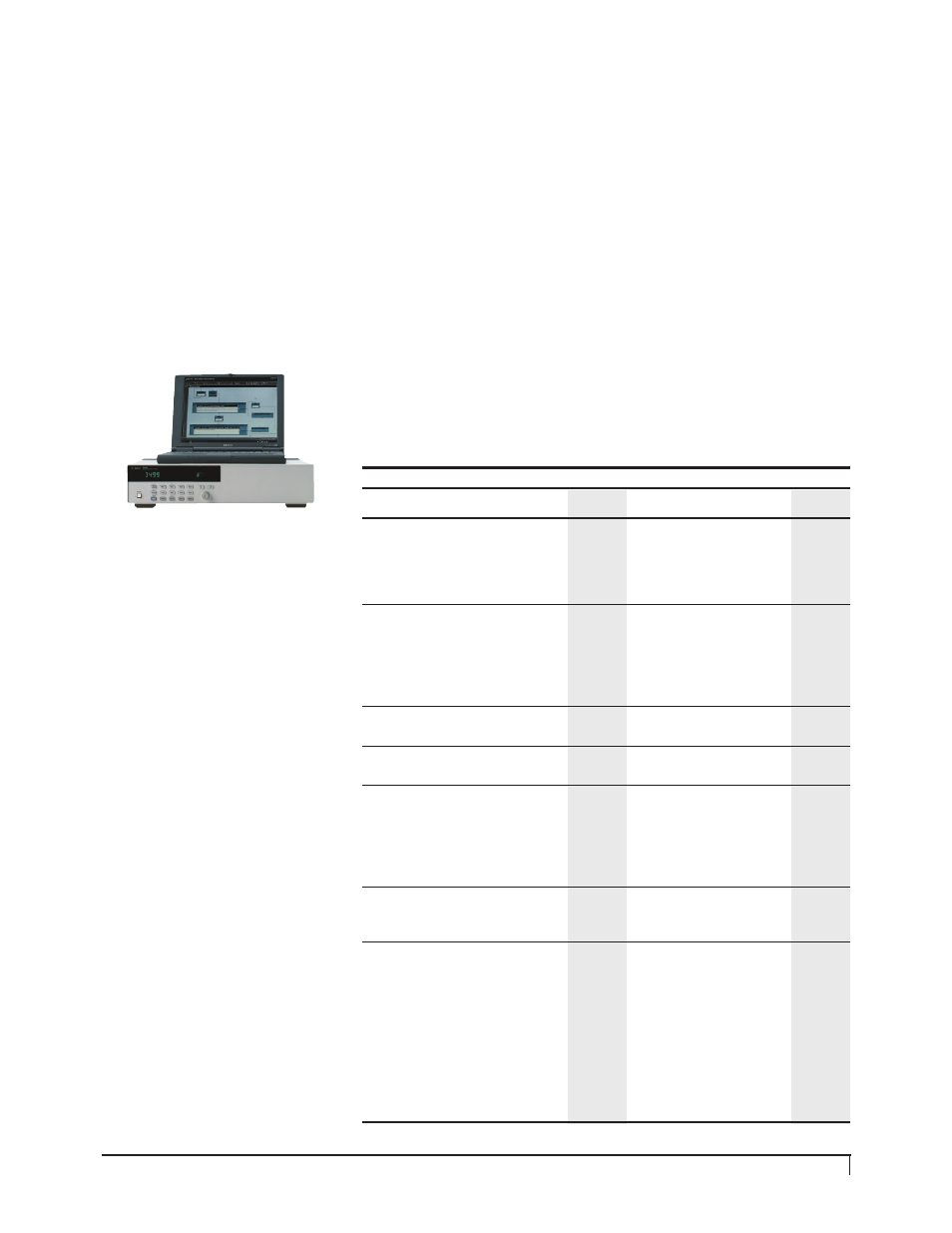
3499A/B/C
User Interface
The 3499A/B/C is easy to manually
control by pushing front-panel
buttons, or program using SCPI
(Standard Commands for Program-
mable Instruments) commands,
HP 3488A commands or the con-
venient Plug&Play or IVI drivers.
The 3499A/B/C user interfaces
can control switch states as well
as implement the scan and moni-
toring features.
Measurements
The 3499A/B/C provides a wide
assortment of switch capability as
well as Digital I/O and DAC. The
3499A/B/C is a valued component
in electronics test systems for
connecting instruments such as
DMMs, counters, spectrum analyz-
ers, LCR meters, signal sources,
power supplies and oscilloscopes.
The 3499A/B/C can also be used
for applications that require
microwave, and optics switching.
Innovative parallel driving circuits
are used in the 3499A/B/C mod-
ules to open/close switches simul-
taneously, which significantly
increases test throughput. The
3499A/B/C does not have an inter-
nal integrated DMM for making
measurements as the 34970A does.
Scanning & Monitoring
The 3499A/B/C can be program-
med to perform a channel scan, or
channel monitoring either from
the front panel, or by using software
commands. Up to 200 channels
and/or bits can be included in one
scan list. Once a scan is set up,
the user can select an arm source,
a trigger source, the number of
sweeps, and the delay time for
each individual channel.
The 3499A/B/C monitor feature
allows users to continuously moni-
tor a selected switch or module
status from the front display. The
3499A/B/C status can be a specific
switching channel, a digital I/O
port, or the state of all switches or
digital I/O on one plug-in module.
A single channel can be monitored
continuously even during an
instrument scan.
The 3499A/B/C is able to store
and recall instrument setups. The
instrument setups include the sta-
tus of relay channels, and/or the
static digital I/O state, module con-
figuration, as well as scanning
setups (scan lists, arm count,
arm source, etc.). Table 3 below
includes the scan rates for the
34970A and 3499A/B/C modules.
34970A
3499A/B/C
Module Type
Modules
Scan Rate
Modules
Scan Rate
Ch/s
Ch/s
Multiplexer
34901A 20 Ch armature
120
N2260A 40 Ch armature
80
34902A 20 Ch reed
120
N2266A 40 Ch reed
350
34908A 40 Ch 1
70
N2270A 10 Ch 1000V
100
wire armature
44470A 10 Ch
43
44470D 20 Ch
43
General
34903A 20 Ch
120
N2261A 40 Ch
80
Purpose
N2267A 8 Ch, 8A
20
Switch
44471A 10 Ch
43
44471D 20 Ch
43
44477A 7 Ch SPDT
43
(Form C)
Matrix
34904A 4x8
120
N2262A 4x8
80
44473A 4x4
43
Digital I/O
N2263A 32-bit TTL
44474A 16-bit TTL
Multifunction 34907A Two 8-bit Dig I/O,
N2264A 12 GP, 3 GP 5A,
80
26-bit Event Counter,
16-bit Dig I/O
Two 16-bit Analog out
N2265A 4x4 matrix,
80
16-bit Dig I/O
N2269A 2 DAC,
80
16-bit Dig I/O
Fiber-Optical N2280A Quad
1x2
50
Multiplexer
N2281A Dual 1x4
40
N2282A Single 1x8
4
RF &
34905A Dual 4 Ch 2G 50
Ω 60
N2268A Dual 1x4 3.5G 50
Ω
20
Microwave
34906A Dual 4 Ch 2G 75
Ω 60
N2272A Single 1x9 1.0G 50
Ω
N2276A Dual 1x6 20G 50
Ω
40
N2276B Relay Driver
40
(2 switches)
44472A Dual 1x4 300M 50
Ω
43
44478A Dual 1x4 1.3G 50
Ω
43
44478B Dual 1x4 1.3G 75
Ω
43
44476A Triple 1x2 18G 50
Ω
43
44476B Relay driver
43
(2 switches)
Table 3. 34970A and 3499A/B/C module scan rates