Atec Agilent-34970A-3499ABC User Manual
Page 4
4
Controlling the Switch Systems
and Making Measurements
The 34970A and 3499A/B/C both
use switching plug-in modules to
route signals to and from your test
system or multiplex signals to
external instruments. Measure-
ments and instrument control
capabilities of the 34970A and
3499A/B/C are what really differ-
entiate the products from one
another. The measurement capabil-
ities, control, monitoring ability,
and channel-scan rates for each of
the systems are included in this
section. Comparing this informa-
tion to the needs of your applica-
tion will make it easy for you to
identify which one of these sys-
tems is best for your application.
34970A
User Interface
The 34970A is easy to manually
control by pushing front-panel
buttons, or program using SCPI
(Standard Commands for Program-
mable Instruments) commands, or
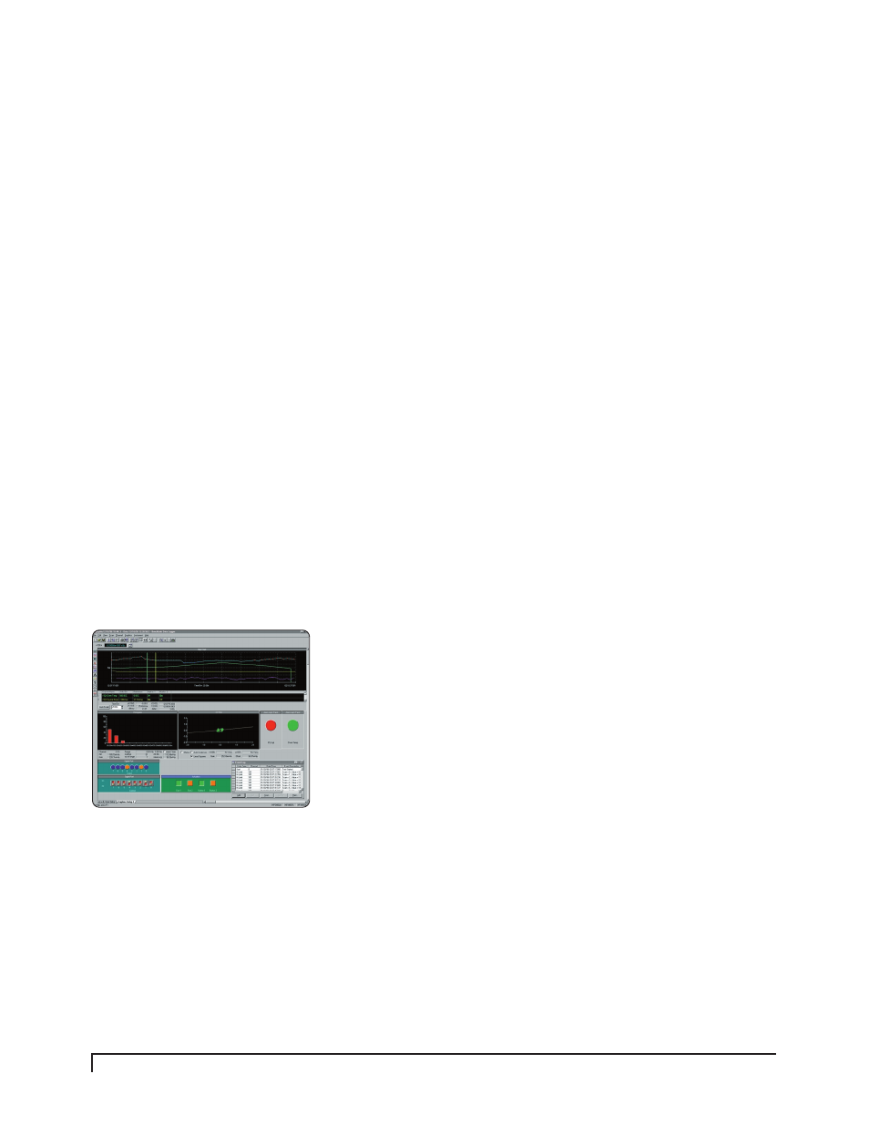
the Plug&Play driver. BenchLink
Data Logger is a PC-based software
that comes with the 34970A. The
BenchLink Data Logger software
provides an easy way to set-up a
test to acquire measurement data.
The 34970A can store the data or
it can perform real-time display
and analysis of the incoming
measurements. These user inter-
faces can be used to make meas-
urements, control switch states,
or implement the scan and/or
monitor features.
Measurements & Alarms
The 34970A mainframe includes a
DMM that works in conjunction
with the Multiplexer plug-in mod-
ules 34901A, 34902A, and 34908A.
Up to 11 different measurements
(listed below) and engineering unit
conversions can be made using
these modules in the 34970A. The
34970A also has the capability to
flag any out-of range measurements
by comparing the input signals with
four different configurable limits
and activating an alarm.
34970A Measurements
• Temperature measured with
Thermocouples, RTDs, and
Thermistors
• DC and AC volts
• 2- and 4-wire Resistance
• Frequency and Period
• DC and AC current
• 4 alarms for High/Low or both
limits for each channel
• Digital I/O
• Analog outputs (DAC)
Scanning & Monitoring
The 34970A allows you to combine
a DMM (either internal or exter-
nal) with the multiplexer channels
to create a scan. During a scan,
the instrument connects the DMM
to the configured multiplexer
channels one at a time and makes
a measurement on each channel.
Automatic scanning and channel
monitoring can be started by man-
ually pressing a front-panel button,
by sending a software command,
an external TTL trigger pulse, an
alarm-initiated action, or an inter-
nally paced timer. During a scan
you can store up to 50,000 readings
in non-volatile memory. Each time
a new scan is started the 34970A
clears all the reading stored in
memory from the previous scan.
Since the 34970A switching is per-
formed as a scanner where only
one channel is closed at any time,
it may be important to your test
system to achieve or exceed a spe-
cific scan rate. Switching scan
rates for the 34970A modules are
shown in Table 3 at right. The
measurement scan rates vary
depending on the type of measure-
ment being made. See the 34970A
data sheet for measurement scan
rate details.
Continuous monitoring of a select-
ed channel, configured for meas-
urement, scan or digital I/O, can
be displayed even during a scan.
The 34970A takes readings on the
single channel as often as it can.
The readings displayed by the
monitor are not stored in memory
but the readings concurrently
taken during a scan will be stored
in memory.