2 rectifier operational status, Ac on, Dc on – Alpha Technologies ACS HP Series User Manual
Page 18: Alarm, Fig. 3-1, rectifier leds 3.0 operation
18
AIP900-0012-B0-001 Rev. A (01/2012)
For detailed installation, operation and fault diagnosis information, refer to the Cordex 125-
4.4kW Modular Switched Mode Rectifier technical manual (p/n 010-589-B2).
NOTE:
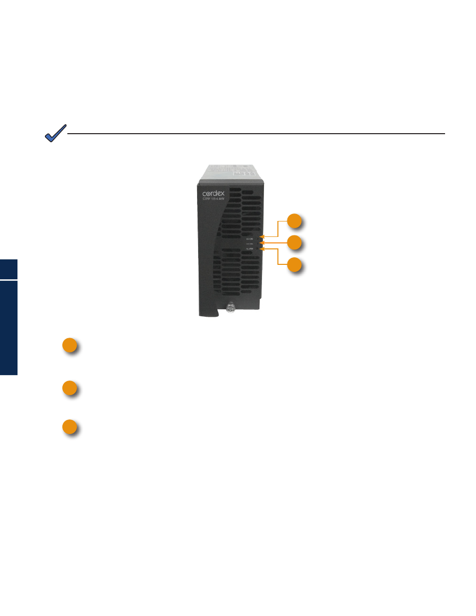
3.2 Rectifier Operational Status
The front panel LEDs provide:
Rectifier Status Summary
Rectifier software upgrade in-progress indication
Locate Module Pattern
Rectifier status summary will show the rectifier alarm status, communication fail status and
rectifier on/off status.
AC ON
The top LED (green) is on when AC is within valid range. The LED will flash (~2Hz) when AC is outside
the normal range - AC voltage is invalid if the AC Mains Low or AC Mains High alarm is active. The
LED turns off when AC has failed.
DC ON
The middle LED (green) is on when the rectifier is delivering power to the load. The LED will flash when
communication is lost. The LED turns off when the rectifier is off; e.g., when commanded via the CXC
Alarm
The bottom LED (red) will flash in the event of an active Module Fail alarm; if the module is unable to
source power as a result of any of the following conditions:
Output fuse blown
AC Mains Input Fail
Module Fail (ramp test fail)
High voltage (OVP) shutdown
Thermal shutdown
Local shutdown
UPF fail
No output power
Fan 1 and 2 fail
The LED will flash (~2Hz) when a minor alarm is detected; if the module’s output capability has been
reduced or a minor component failure has been detected during the following conditions:
VAC meter fail
AC foldback
Remote equalize
Fan (1 or 2) fail
Low output voltage
High output voltage
Current limit (programmable option)
Power limit (programmable option)
High temperature foldback
Temperature sense fail
Soft start operation
Communications lost
The LED remains off in the absence of an alarm. If the unit output is not connected to a battery or parallel
rectifier, the LED will extinguish if no power is present.
1
2
3
2
3
1
Fig. 3-1, Rectifier LEDs
3.0 Operation