2 recommended installation layout – Alpha Technologies ACS HP Series User Manual
Page 14
14
AIP900-0012-B0-001 Rev. A (01/2012)
2.2 Recommended Installation Layout
Verify input (supply) wiring has been run to site in accordance with applicable local and national
electrical codes.
The ACS Series system is heavy equipment. To prevent personal injury or equipment damage, use lifts
and extreme care when handling.
Ventilation and Cooling:
The rectifier/charger is rated to better perform within 18°F (–10°C) and 122°F (+50°C)
temperature range.
To calculate the required air displacement (exchange) volume, please use the following equation:
V = BTU x e (0.125 x H x Tk/To) / (Tr -Tk)
Where:
V = Air flow: [cubic meter/hour]
BTU: Total dissipated heat
Tr: Maximum allowed room temperature [°K] {i.e. 50°C = 323°K]
Tk= Temperature of input cooling air
To= 273 °K H = Altitude [km]
For adequate ventilation and safe access, verify the following minimum clearances around the charger:
3 in. (10 cm) on the sides and top of the unit.
7 in. (18 cm) in back of the unit.
3 feet (1 meter) in front of the unit.
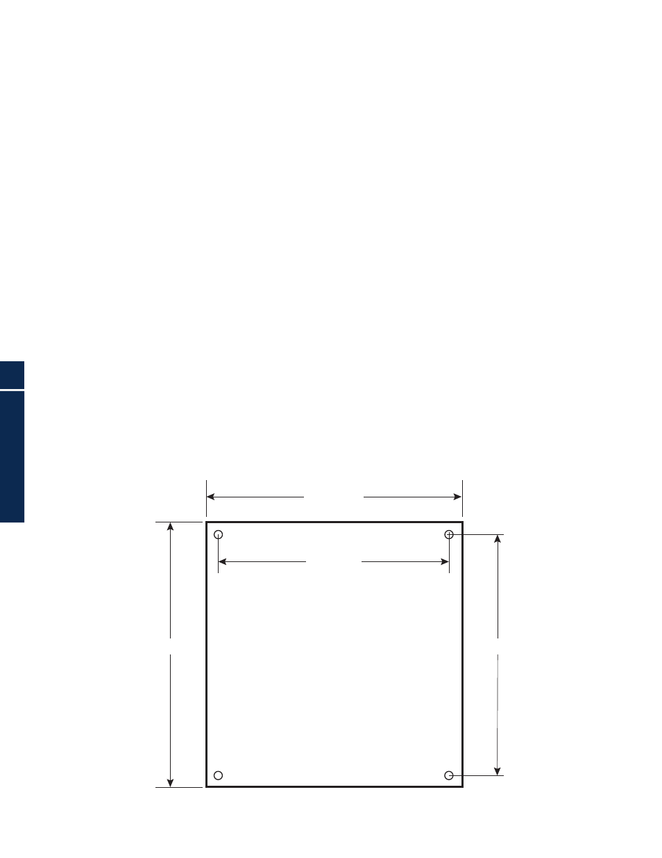
Should seismic conditions require a more secure installation the unit may be bolted to the floor.
Four (4) holes are provided for this purpose.
23.6”/600mm
21.1”/536mm
24.6”/625mm
23”/584mm
Fig. 2-1, Cabinet Footprint with dimensions
2.0 Installation