9 ecm interface block diagram and connectors, 0 the engine control module, continued, Ecm tb2 – Alpha Technologies AlphaGen PN-6x-T 7.5kW 48Vdc User Manual
Page 66
66
042-288-B0-001, Rev. A2
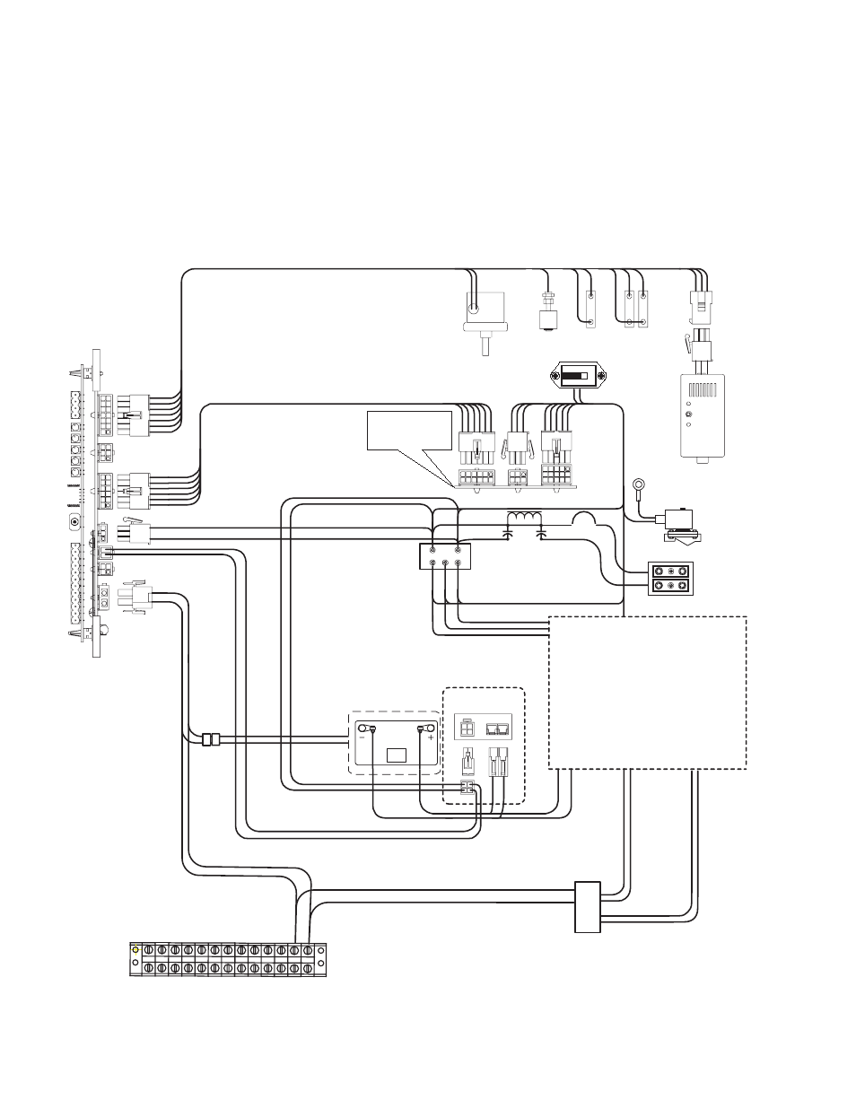
Fig. 4-7, ECM/APU Interconnection
4.0
The Engine Control Module, continued
4.9 ECM Interface Block Diagram and Connectors
The Generator Remote Interface provides power conditioning to the ECM PCB, and
connection between cabinet sensors and the APU control. The interface supplies all
necessary signals, alarms, logic power, and analog voltages required for telemetry at the
central office or relevant monitoring station, and allows the ECM to start and stop the engine
alternator as part of the network controlled periodic test sequence.
1
2
Engine/Alternator
Ignition
Battery
Output
AC
Gen.
Control
Signal s
Fuel
Solenoid
Ga s
Detector
Tamper
Pa d
Shear
Wate r
Intrusion
Ignition
Battery
Ignition
BatteryCharger
Fuel Low
Pressure
Switch
(Propane Only)
Generator
Control Board
Output
Rectifier
QUART Z
00 1
5
Hour
Meter
Battery heater mat
Engine
Block
Heater
Carb
Heater
Duplex
Outlet
NOT A
SERVICE
OUTLET
Inductor
Cap
Cap
PN-6X-T (48V) PI Filter
CB
Pin 1
Pin 1
ECM
TB2