Installation, 5 service power inserter – Alpha Technologies BD-8 User Manual
Page 21
3. Installation
21
031-032-C2-002 Rev. B
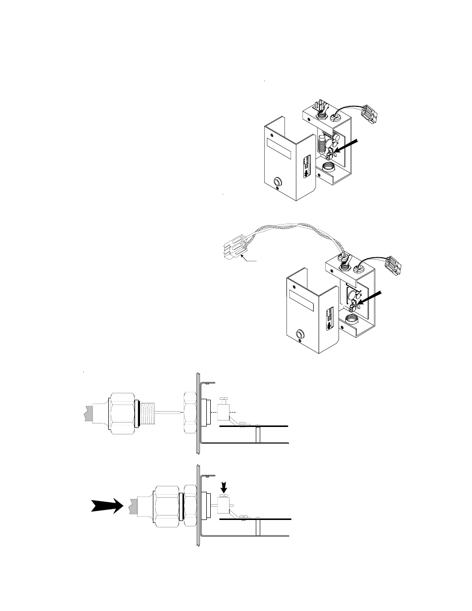
Fig. 3-6 Connecting COAX to SPI Output Port
Fig. 3-5 Removing SPI Cover
3.5
Service Power Inserter
1. The SPI box(es) are mounted on a bracket
behind the top power supply.
2. Remove the two screws on the face of the SPI
and lift off the cover to gain access
to the Seizure Screw Assembly. Loosen the
Seizure Screw several turns so that the stinger
will pass through the clamp (Fig. 3-5).
3. Insert the Coaxial Termination into the output
port on the bottom of the SPI. Verify the
stinger goes through the Seizure Screw
Assembly. Tighten the Coaxial Termination
(Fig. 3-6).
4. Tighten the seizure screw to 35.0 Inch-
Pounds. Replace the SPI cover and
screws. Inadequatly tightened seizure
screws will result in high resistance
contact, increased contact heat, and
possible contact failure.
Verify the switch on the top or the
SPI is in the ON position. The AUX
position is used only when an
alternate power source is
connected to the 'Jones’ (in 15A
rated SPI units) or ‘Innergy’
connector (in 25A rated SPI
units) on the top of the SPI.
Seizure Screw
Assembly
15 Amp-rated SPI
Seizure Screw
Assembly
25 Amp-rated SPI
"Innergy" connector
Seizure Screw
Assembly
Side View of SPI Case
Circuit Board
Coaxial Termination
Stinger
Enclosure
Wall
Output
Port