Installation – Alpha Technologies BD-8 User Manual
Page 19
3. Installation
19
031-032-C2-002 Rev. B
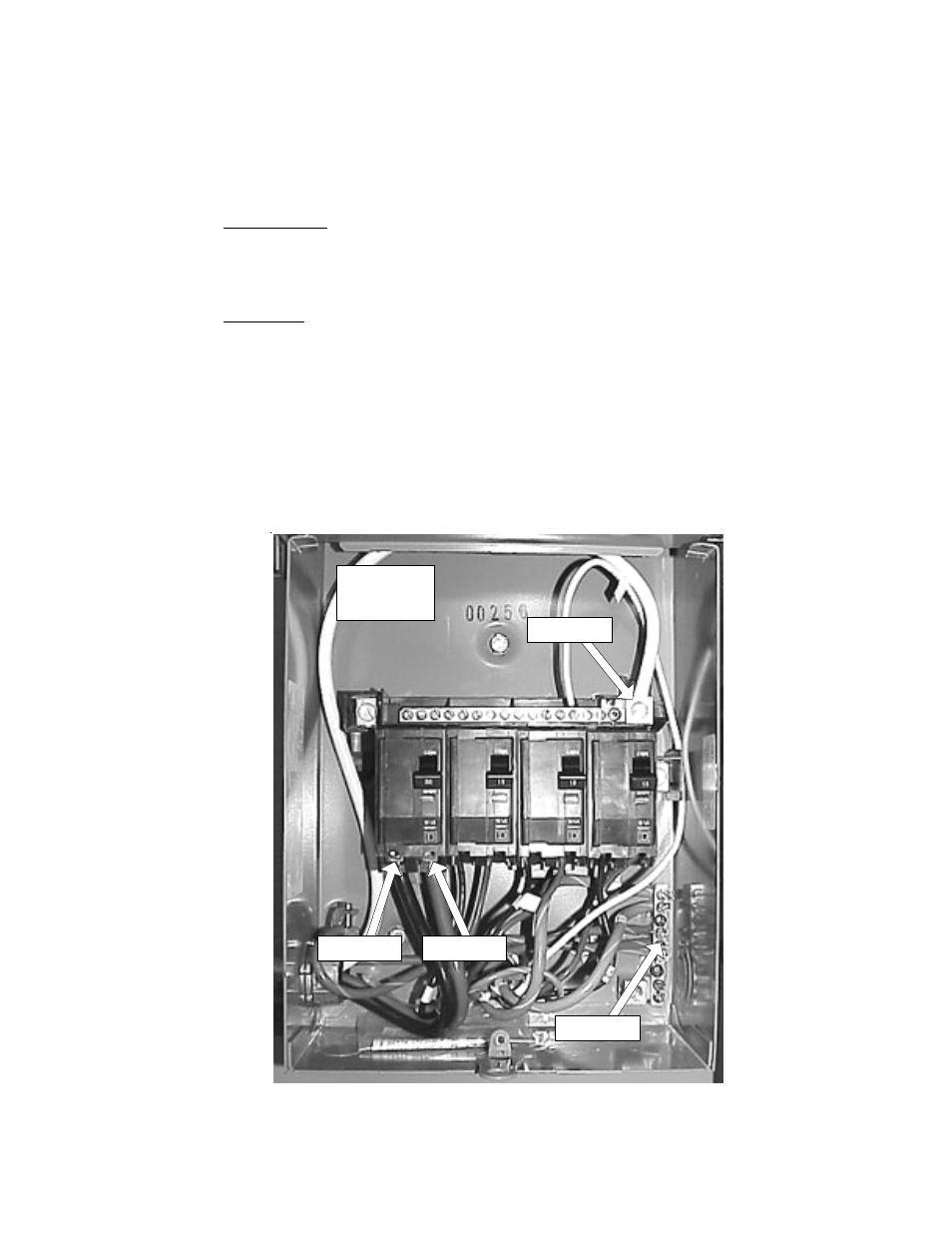
Fig. 3-3 Service Entrance Wiring
Tools Needed:
No. 1 Flat Head Screwdriver
Adjustable Pliers (Channel-Lock)
Procedure:
3.4.1
Electrical Service Connection,
continued
3.4
Utility Powering,
continued
1. Locate the service entrance panel on the enclosure (exterior). Remove the
cover to access the circuit breaker assembly. If this service panel is to be
used as the primary service entrance, neutral must be bonded to ground.
2. Connect one of the black #6 wires to the bottom of the left side of the
input circuit breaker (Line 1), and the remaining black (or red) #6 wire to
the right side of the input circuit breaker (Line 2). Connect the #6 white wire
to the top of the neutral bus to the right of the circuit breakers.
Neutral
Line 1
Line 2
Ground
240 VAC
Installation