Al 2-light, Technical installation data – Alera Lighting AL 2-Light User Manual
Page 2
Page 2/4 Rev. 01/14/14
RECESSED / AL 2-LIGHT TID
AL 2-LIGHT
Technical Installation Data
© 2014 Alera Lighting, a division of Hubbell Lighting, Inc. Specifications subject to change without notice.
701 Millennium Blvd. Greenville, SC 29607 / Tel 864.678.1000 / Website www.aleralighting.com
Electrical
1. Starting from right end of row (facing wall), snap in place electrical unit, starting with the shortest unit and progressing to the longest unit.
2. Each unit has polarized plug-in connector. After wire connections, secure units together with connector plate that slips over lampholders.
Screws are provided.
3. Power feed is at end of row. Clip off plug to make connections. Install service cover and electrical end assembly.
4. Determine length for snap-on wireway cover for
adjustable unit. Cut wireway cover, plug in wiring connection and snap adjustable unit
into place.
5. Install
clip to hold Adjustable Unit in place.
6. Install lamps.
7. Install
lamp shield.
8. Where required, snap in
reflectors. Reflectors overlap at adjustable unit.
Diffusers
1. Install plastic shielding baffle or parabolic louver. Cut last piece to fit.
Note: On parabolic louver, it may be necessary to cut the last
two (2) louvers to maintain an even louver spacing appearance.
2. Plastic or baffle lays in place: parabolic louver cantilevers off lip trim rail.
3.
Important: Cut final plastic piece after sufficient lamp or building warm-up to allow for plastic expansion.
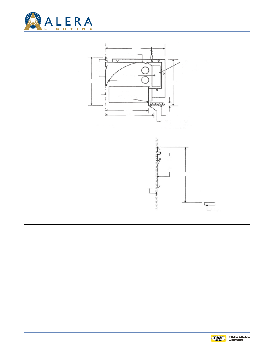
"AL" Housing (Chassis)
12"
Access to ceiling for wiring and
J-box inspection must be cut in
housing by installing contractor
Install drywall into fixture
trim and secure other end to
building structure
Ceiling Tile (by others)
1"
10"
81/2"
9
15
/
32
"
103/8"
Wall
Wall
Rail
Wall
Plate
Reflector
Electrical Unit
Parabolic Louver
Non-supporting
fixture trim
AL-2T8P-R-LD
1. Mount wall rail to wall 103/8" from finished ceiling
plane to top of wall rail. Fasteners not provided. Wall rail
furnished in 90" sections.
2. Where applicable, hook wall plate over bottom lip of
wall rail and fasten to wall.
3. Install AL components per instructions.
4. Important: To save steps and time:
A. Start at the right end of each row facing the wall and
work left and
B. Install smallest (lower wattage) housings and electrical
units first and then work up to the largest units.
INSTALLATION DATA
Step One - Install Wall Rail
103/8"
Ceiling Plate
Wall Plate
Wall Rail
Wall