ABUS TV8720 User Manual
Page 12
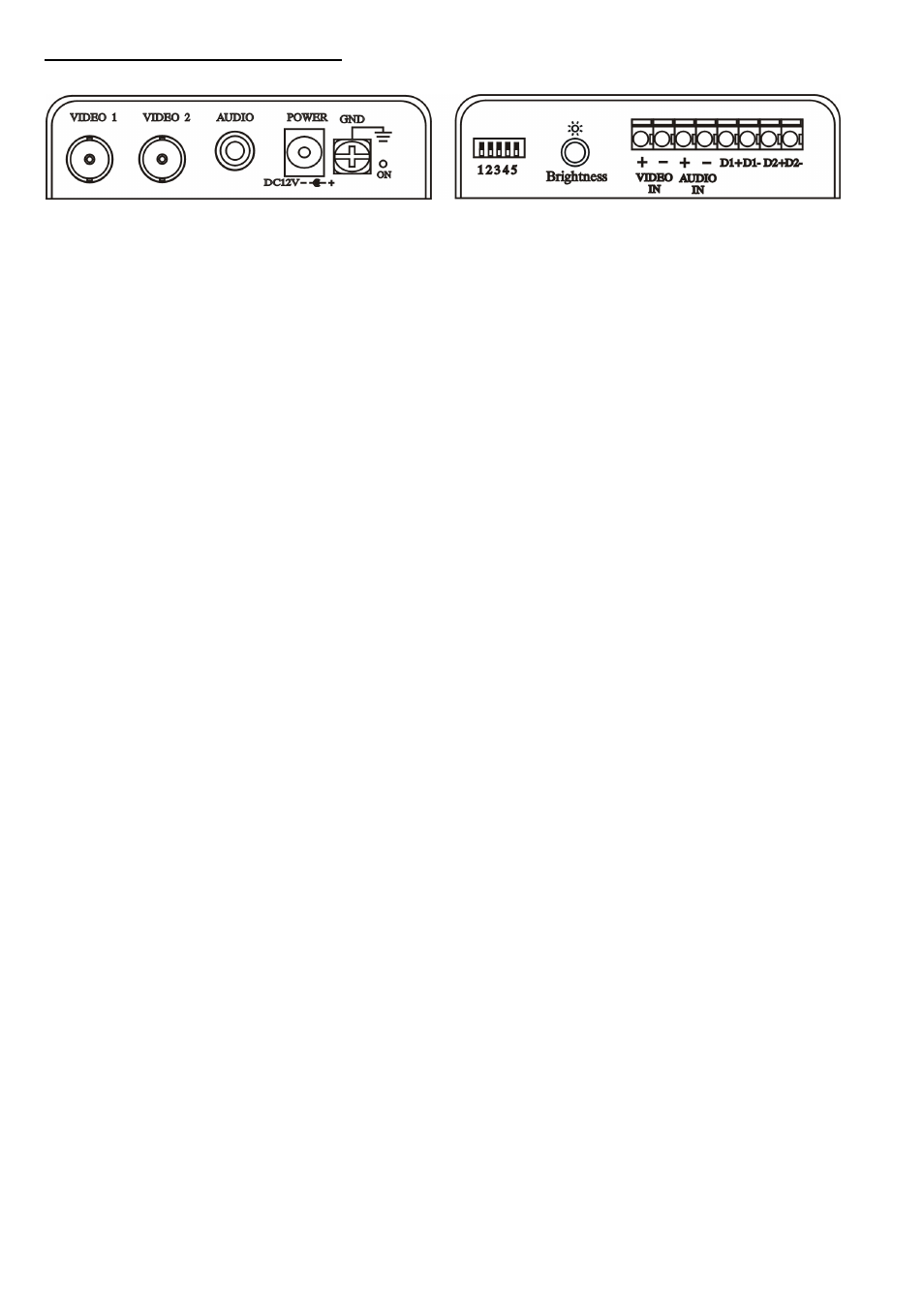
4. TV8720 connection diagram (continued)
Receiver module, front side
Receiver module, rear side
Connections as on receiver module –
Connections as on receiver module –
Front
Rear:
Video 1 – composite (FBAS) video output 1
12345 – range adjustment
Video 2 – composite (FBAS) video output 2
Brightness – fine adjustment
Audio – audio output
Video IN – clamp for twisted-pair transmission
Power – 12VDC input for transformer
Audio IN – clamp for twisted-pair transmission
GND – housing grounding
D1+/D1-
–
output for alarm contact (NO)
D2+/D2-
–
input for data line (RS485)
The maximum distance between a sender and receiver module (depending on selected setting) must not exceed 1,500m. Make sure that you do
not lay the connection line near electrical power lines – in rare cases their proximity may lead to interference (poor picture quality).
12
- CASA30400 (46 pages)
- CASA30500 Quick installation instructions (44 pages)
- TVIP10005B (125 pages)
- TV7181 (44 pages)
- TVCC40531 (75 pages)
- TV7511 (54 pages)
- TV7018 (56 pages)
- TVCC12020 (28 pages)
- TVCC12010 (48 pages)
- TVCC40010 (104 pages)
- TVCC34010 (104 pages)
- TVIP61500 Operating instructions (487 pages)
- TVIP61500 Quick operating instructions (124 pages)
- TVCC40000–TVCC40030 (62 pages)
- TVIP41500 Operating instructions (498 pages)
- TVCC35500 (63 pages)
- TVCC70000 (83 pages)
- TVCC75100 (248 pages)
- TVCC60000-TVCC60030 (84 pages)
- TV3210 (171 pages)
- TVVR30004 Operating instructions (569 pages)
- TVVR30004 Quick operating instructions (162 pages)
- TVAC15000B (87 pages)
- TVAC16000B (139 pages)
- TVAC15010B (44 pages)
- TVAC16010B (43 pages)
- TVAC80010B (68 pages)
- TVVR11002 (134 pages)
- TVAC710x0 (90 pages)
- TV6700 (60 pages)
- TVAC35500–TVAC35520 (52 pages)
- TVAC35600 (48 pages)
- TVAC21000 (98 pages)
- TVAC10000 (92 pages)
- TVAC10100 (76 pages)
- TVAC10041 Operating instructions (99 pages)
- TVAC10041 Quick operating instructions (50 pages)
- TVAC10050 Operating instructions (117 pages)
- TVAC10050 Quick operating instructions (50 pages)
- TVAC10021 Operating instructions (105 pages)
- TVAC10021 Quick operating instructions (50 pages)
- TV8740 (24 pages)
- TVVR41220 Quick operating instructions (87 pages)
- TVVR41220 Operating instructions (409 pages)
- TVAC312x0 Quick operating instructions (146 pages)