AAEON ACP-1103 User Manual
Page 110
M u l t i - T o u c h P a n e l P C
A C P - 1 1 0 3
Appendix E Digital I/O Ports
E-2
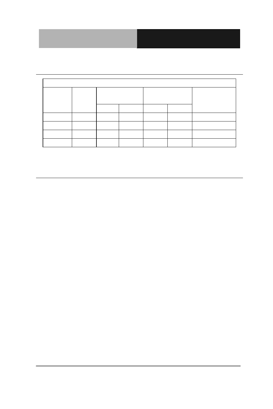
E.1 Electrical Specifications for Digital I/O Ports
Table 1 : Digital Input/Output Pin Electrical Specification
Pin
Type
Input Threshold
Voltage
Output Voltage
Note
Low
High
Low
High
DIO1
I/O
0.8
2.0
0
3.3
DIO2
I/O
0.8
2.0
0
3.3
DIO3
I/O
0.8
2.0
0
3.3
DIO4
I/O
0.8
2.0
0
3.3
Note: All DIO pins are 5V tolerance in input mode.
E.2 DIO Programming
ACP-1103 utilizes FINTEK F81801U chipset as its Digital I/O
controller. Below are the procedures to complete its configuration
and the AAEON initial DIO program is also attached based on
which you can develop customized program to fit your application.
There are three steps to complete the configuration setup: (1) Enter
the MB PnP Mode; (2) Modify the data of configuration registers; (3)
Exit the MB PnP Mode. Undesired result may occur if the MB PnP
Mode is not exited normally.