2 internal connectors, Internal connectors -15 – AAEON IMBM-Q67A User Manual
Page 23
2-15
Chapter 2: Motherboard information
Audio 2, 4, 6, 8-channel configuration
Port
2-channel
4-channel
6-channel
8-channel
Light Blue (Rear
panel)
Line In
Rear Speaker Out Rear Speaker Out Rear Speaker Out
Lime (Rear panel) Line Out Front Speaker Out Front Speaker Out Front Speaker Out
Pink (Rear panel)
Mic In
Mic In
Bass/Center
Bass/Center
Lime (Front panel)
-
-
-
Side Speaker Out
7. USB 2.0 ports. These two 4-pin Universal Serial Bus (USB) ports are
available for connecting USB 2.0/1.1 devices.
8. DVI-D port. This port is for any DVI-D compatible device. DVI-D can’t be
converted to output RGB Signal to CRT and isn’t compatible with DVI-I.
9. DisplayPort. This port connects a display monitor or a home-theater system.
10. PS/2 Keyboard port (purple). This port is for a PS/2 keyboard.
2.7.2
Internal connectors
1.
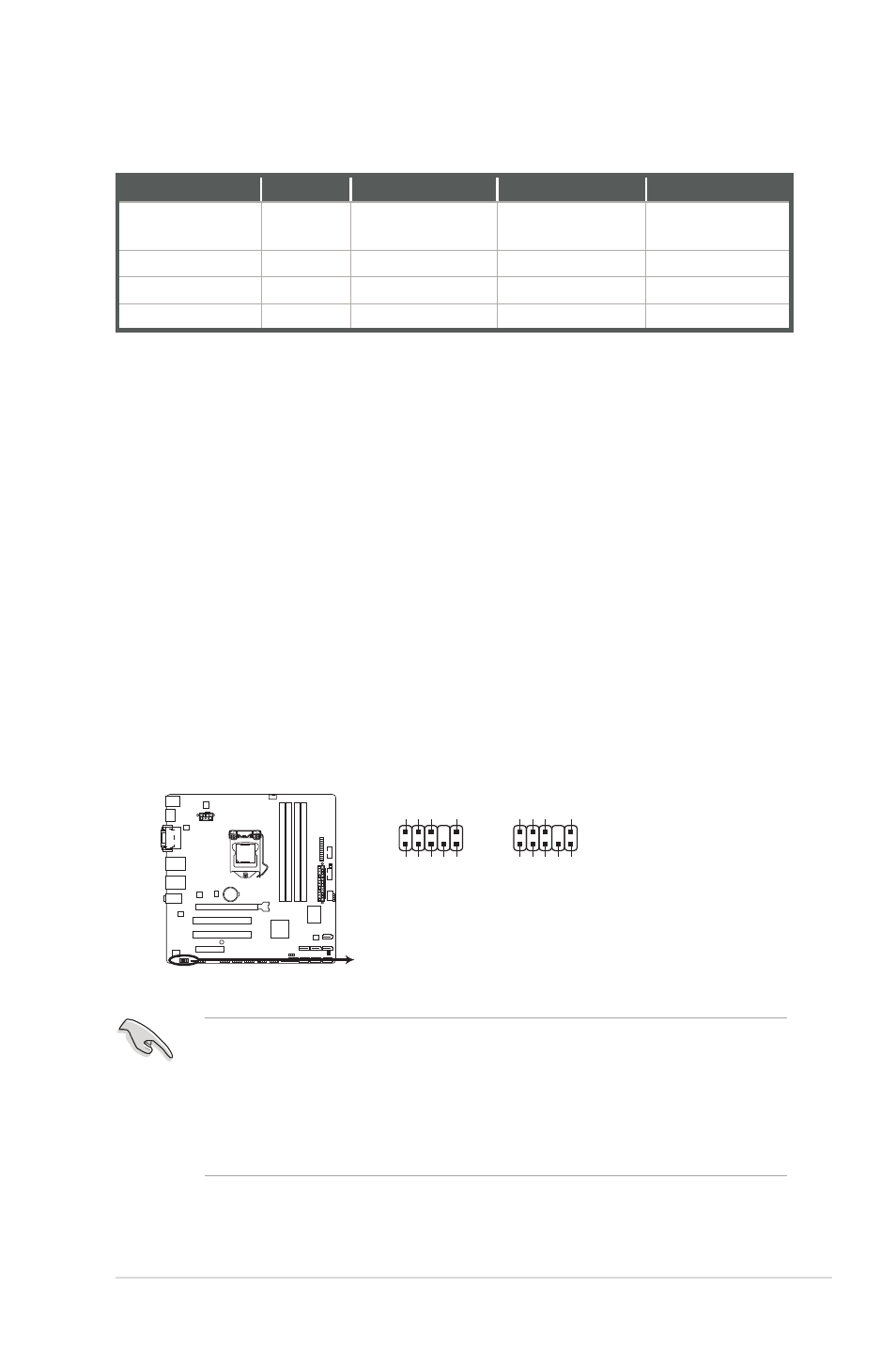
Front panel audio connector (10-1 pin AAFP)
This connector is for a chassis-mounted front panel audio I/O module that supports
either HD Audio or legacy AC`97 audio standard. Connect one end of the front panel
audio I/O module cable to this connector.
• We recommend that you connect a high-definition front panel audio module to this
connector to avail of the motherboard’s high-definition audio capability.
• If you want to connect a high-definition front panel audio module to this connector,
set the Front Panel Type item in the BIOS setup to [HD]. If you want to connect an
AC'97 front panel audio module to this connector, set the item to [AC97]. By default,
this connector is set to [HD]. See section 3.4.10 Onboard Devices Configuration for
details.
IMBM-Q67A
IMBM-Q67A Front panel audio connector
AAFP
AGND NC SENSE1_RETUR
SENSE2_RETUR
PORT1 L PORT1 R PORT2 R
SENSE_SEND
PORT2 L
HD-audio-compliant
pin definition
PIN 1
AGND NC NC
NC
MIC2
MICPWR Line out_R
NC
Line out_L
Legacy AC’97
compliant definition