Elmo Rietschle L-BL2 User Manual
Page 3
System design
© Gardner Denver Deutschland GmbH
3 / 36
610.44444.40.000
System design
012
010
064
025
080
032
079
058
057
052
027
F
D
E
B
A
005
095
007
096
030
037
001
C
019
066
065
023
G
K
040
041
J
043
031
039
H
086
085
060
007
025
025
060
2BL2 251, 281, 341
2BL2 141
L_300
K
J
E
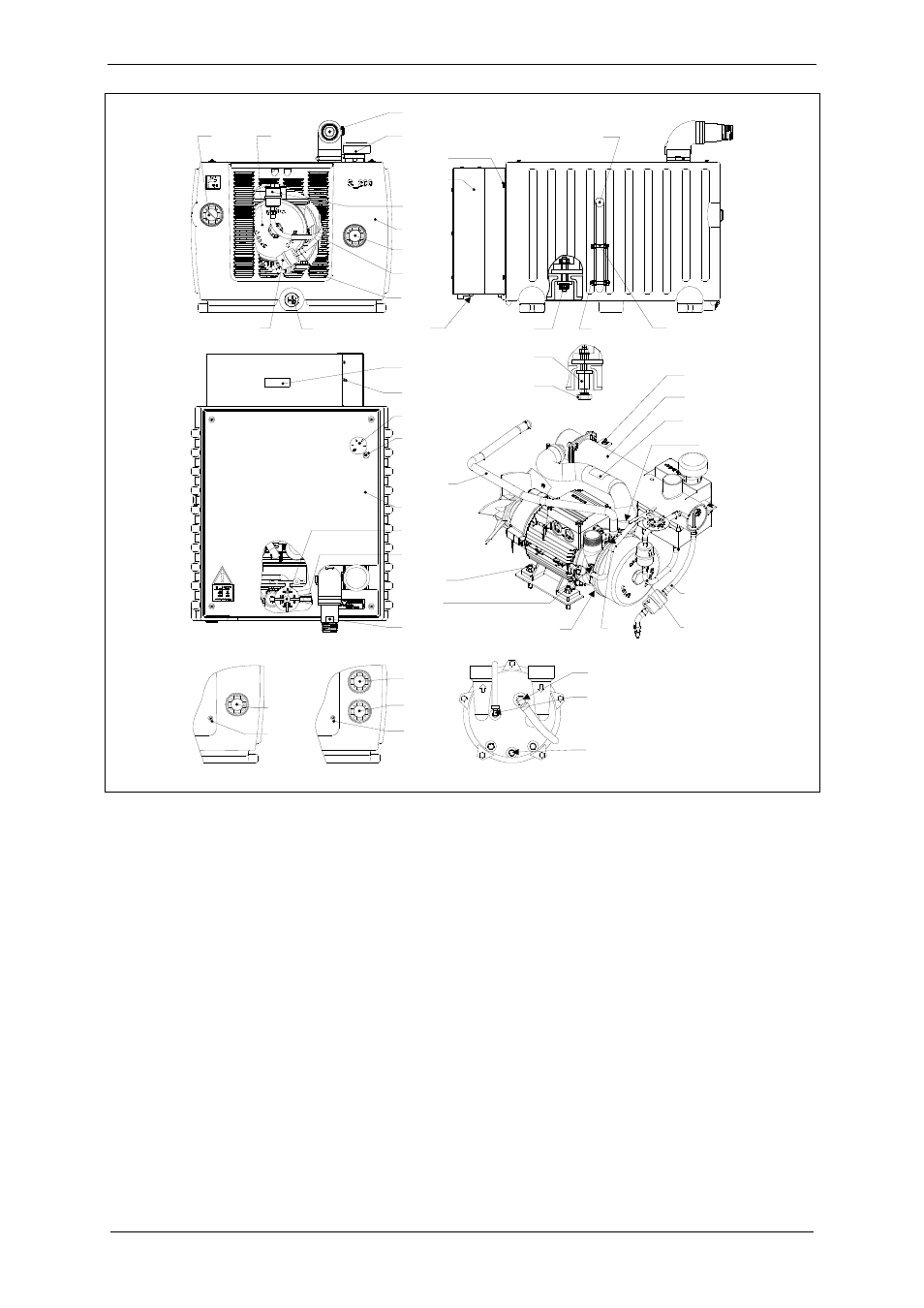
Fig. 1: System design
A Inlet
connection
027
Water or air water cooler
B Exhaust-air
connection
030 Screw
C Cable
inlet
031 Condensation
cooler
D
Installed unit (L-BV7 pump)
032 Screw
E
Draining installed unit
037 Connecting
piece
F Draining
cooler
039
Intake hose with check valve
G
3-way valve (only 2BL2 041 to 2BL2 141)
040 Injection
water
pipe
H
Screw-in connecting sleeve
041 Condensate
pipe
J
Operating liquid hole
043
Operating liquid pipe
K
Cavitation protection hole
052 Rating
plate
057 Screw
058 Protective
screen
001 U-separator
060 Screw
005 Drain
opening
064 Cover
plate
007
Filling opening and connection for drain
controller
065 Cord
grip
010
Fill level indicator
066 Screw
012 Screw
079
Restrictor sleeve for water pipe
019 Nut
080
Restrictor sleeve for air pipe
023 Nut
095 Water
filter
025
Connection for supply or drain controller
096 Air
filter