Elmo Rietschle L-BL2 User Manual
Page 15
Installation
© Gardner Denver Deutschland GmbH
15 / 36
610.44444.40.000
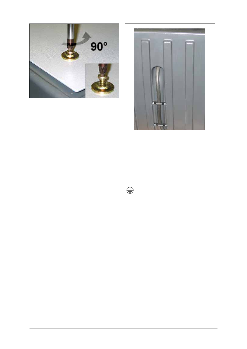
Fig. 5: Remove cover plate:
Unscrew screws
Insert the connecting cable:
Thread the connecting cable into the cord
grips on the side panel of the separator and
push it through the cable inlet into the interior
of the separator.
Route the connecting cable into the terminal
box of the installed unit via the cable entry
opening.
In order to relieve strain, secure the
connecting cable as follows:
–
via the cable gland on the terminal box of
the installed unit
–
via the cord grips on the outside of the
separator
–
Tightening torques: see Chapter 3.1,
"Mechanical data", Section "Tightening
torques", Pg. 9.
Fig. 6: Strain relief:
Cord grips on the outside of the separator
Connection to drive-motor terminal box:
Carry out the connection and the arrangement of
the jumpers in accordance with the circuit
diagram in the terminal box.
Connect the protective conductor to the terminal
with the following symbol:
The electrical connection must be carried out as
follows:
The electrical connection must be
permanently safe.
There may be no protruding wire ends.
Clearance between bare live parts and
between bare live parts and ground: ≥ 5.5 mm
[0.217"] (at a nominal voltage of UN ≤ 690 V).
Tightening torques for terminal plate
connections:
see Chapter 3.1, "Mechanical data",
Section "Tightening torques", Pg. 9.
Use suitable cable lugs.
For terminals with clamping straps, the
conductors must be inserted so that
approximately the same clamping height
results on both sides of the bar.
Individual conductors must therefore be bent
into a U-shape or connected with a cable lug.
All conductors under outer angled grounding
brackets must be bent into a "U" shape.