Elmo Rietschle L-BL2 User Manual
Page 13
Installation
© Gardner Denver Deutschland GmbH
13 / 36
610.44444.40.000
1
2
3
3
3
E
F
B
A
D
C
C
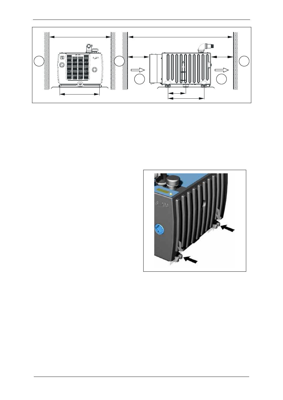
Fig. 3: Minimum distances for heat dissipation and spacing of securing eyes
A – C: Minimum clearance for heat dissipation
D – F: Spacing of securing eyes
See Chapter 3.1, "Mechanical data", Pg. 8 for
dimensions.
1
Cooling
air
inlet
2 Cooling air outlet
3 Wall
Installation conditions:
The system must be installed as follows:
on flat, level surfaces,
on stationary (fixed) surfaces or structures,
with the feet facing downward (no ringing off,
e.g. with the feet on the wall),
at a maximum height of 1000 m [3280 ft]
above sea level.
At installation altitudes of more than 1,000 m
[3,280 ft] above sea level, the Service
Department must be consulted.
Observe the following when installing the system:
The
load-bearing capacity
of the installation
surface must at least be designed for the
weight of the system.
The
vibration behaviour at the operating
location
must be taken into account.
The total vibrations of the system are
dependent on the following factors:
–
the characteristic vibrations of the system,
–
the alignment and installation,
–
the condition (vibration behaviour) of the
load-bearing surface,
–
the influences by vibrations of other parts
and system components (external
vibrations).
The maximum permissible value for vibrations
is v
eff
= 4.5 mm/s [0.177"/s].
To ensure proper operation and a long service
life of the system, this value may not be
exceeded.
Generally, this value can be adhered to
without a special foundation or a special base
plate.
The points on the system for measuring the
vibration speed are shown in Fig. 4, Pg. 13.
Fig. 4: Points for measuring the vibration
speed