Operation and maintenance – Liberty Pumps SBX-Series User Manual
Page 6
©Copyright 2013 Liberty Pumps Inc. All rights reserved 6
TEMPORARY
MANUAL
OPERATION
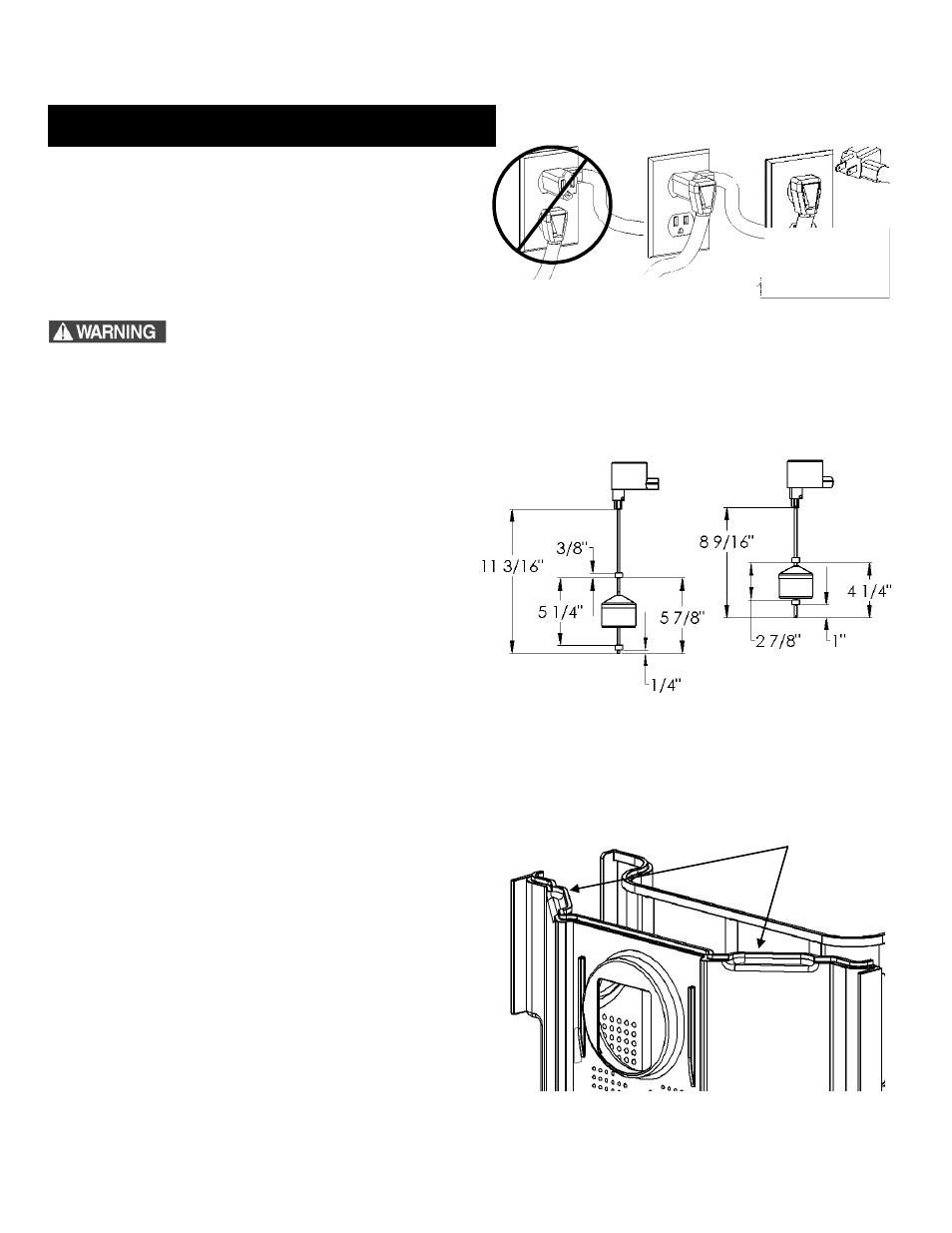
DO!
DON’T!
Fig. 6 Piggyback plug installation.
Fig. 7 Pump and Alarm Switch Set Points
Pump Switch
Alarm Switch
Fig. 8 Removal of Strainer Basket
Take hold of these
handles and lift the
strainer upward out
of the basin.
A. For automatic operation, the two cords should be
interconnected and plugged (see fig. 6) into a separately
fused, grounded outlet of proper amp capacity for your
selected pump model (see Section 1, General
Information, or the pump nameplate for electrical
specifications of your model.) Both cords are equipped
with 3-prong plugs and must be plugged into a properly
grounded 3-wire receptacle.
DO NOT REMOVE GROUND PRONGS FROM ATTACHMENT PLUGS.
B. Pump and alarm switch
levels are preset at the factory. If
for any reason the switch levels change, please refer to fig.
7 for proper re-adjustment of the switch. It is
recommended that the system be disconnected from the
power source and the switch be removed to perform this
operation. Periodically check the condition of the switches
to ensure proper operation by removing debris or build up
that would render the switch inoperable.
C. To clean the strainer basket, loosen the two wing bolts and
remove the access cover. Lift up on the two handles (see
fig.8) and remove the strainer basket. Caution: water will
continue to drip from strainer after removal. Clean the
basket by dumping the debris and rinsing. Reinstall the
strainer basket as soon as possible to prevent debris from
entering the tank. Reinstall the access cover. It is strongly
recommended that this be done frequently during new
home construction and every 6 months thereafter or as
needed.
D. To remove a switch, open the access cover and remove the
strainer basket. Remove the appropriate cord grommet on
the secure cover and pull the switch cord through the open
hole. Remove switch bracket using a 7/16” socket or nut
driver (see Figure 10). The switch can now be lifted from its
pocket and be serviced or replaced. To reinstall a switch,
place it back into the float pocket. Route the switch cord
around the internal inlet hub (see fig. 9). The switch cord
should not interfere with filter tray operation. Pull the end of
the switch cord through the grommet hole in the cover and
reinstall the cord grommet.
E. To reinstall a switch,
place it back into the float pocket. Route
the switch cord around the internal inlet hub (see Figure 9).
The switch cord should not interfere with filter tray operation.
Secure switch with switch bracket using a 7/16” socket or nut
driver (see Figure 10). Pull the end of the switch cord through
the grommet hole in the cover and reinstall the cord grommet.
4. Operation and Maintenance