Liberty Pumps SBX-Series User Manual
Page 4
©Copyright 2013 Liberty Pumps Inc. All rights reserved 4
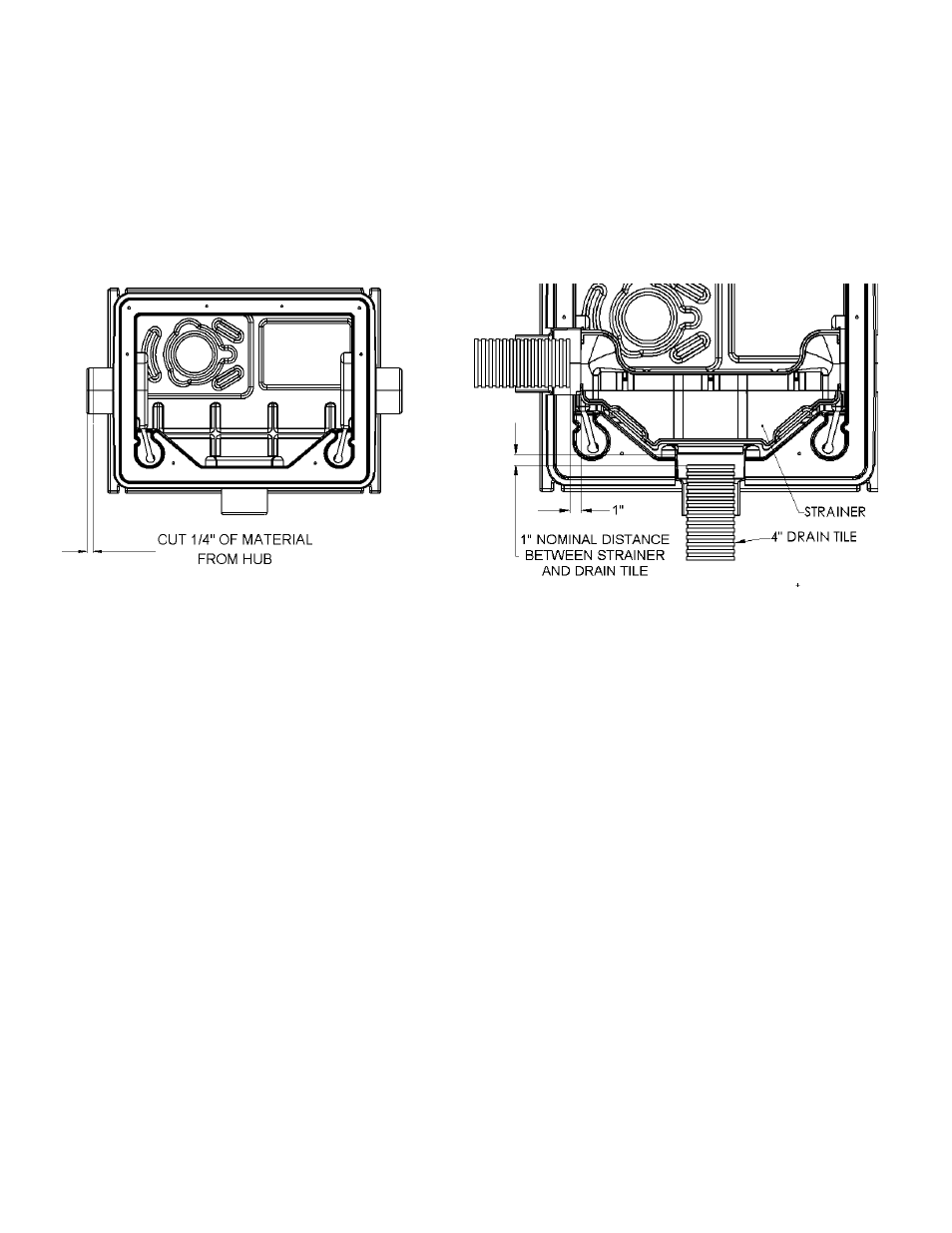
Fig. 2 Cutting the Inlet Hubs
wish to use. Cut 1/4” (but not more than 3/4”) of material from those inlet hubs to assure a good drain tile fit (see fig. 2). Insert the
drain tile into the cut inlet hub. Allow about 1” of spacing between the end of the drain tile and the internal strainer basket for good
operation and easy removal of the strainer during maintenance (see fig. 3).
D.
Final Backfill. Large rocks, clods, and foreign objects should be kept out of the backfill material. Only fine, 1/4" to 3/4" pea gravel,
or 1/8" to 1/2" washed, crushed stone is recommended. Do not use sand or native soil as backfill. Provide access to the basin
cover for maintenance and service.
IMPORTANT: Do not exert heavy pressure or run heavy equipment on the backfill as this could cause damage to the tank.
Finish Plumbing and Alarm Installation
IMPORTANT: All plumbing installations (waste and vent) should done by a qualified professional and in accordance with
applicable codes.
A. Remove and recycle the disposable protective cover before plumbing the system.
B.
NOTE: Threaded connections at cover - HAND TIGHTEN ONLY and use Teflon tape as a thread sealant. Remove the gray
plug and
install 1-1/2” PVC pipe to the cover connection labeled “1-1/2” DISCHARGE” (see figure 4). A union should be installed
to facilitate pump removal if necessary. A free-flow swing check valve is recommended after the union to prevent the backflow of
liquid after each pumping cycle. A gate or ball valve should follow the check valve to allow periodic cleaning of the check valve or
removal of the pump. The remainder of the discharge line should be as short as possible with a minimum number of turns, to
minimize friction head loss. Contact Liberty Pumps or other qualified person if you have questions regarding proper pipe sizes and
flow rates.
C. If your system is equipped with an alarm, refer to the alarm Installation Instructions for proper connection. The alarm box and
accessories are located under the clear protective cover. The alarm switch cord has bare wire leads and exits the cover through
the single hole grommet (see fig. 4).
Fig. 3 Drain Tile Placement