Cla-val, 501a wafer swing check valve – Cla-Val 501A Series User Manual
Page 4
CLA-VAL
Copyright Cla-Val 2011 Printed in USA Specifications subject to change without notice.
P.O. Box 1325
• Newport Beach, CA 92659-0325 • Phone: 949-722-4800 • Fax: 949-548-5441 • E-mail: [email protected] • Website cla-val.com
©
E-501A (R-3/2010)
501A Wafer Swing Check Valve
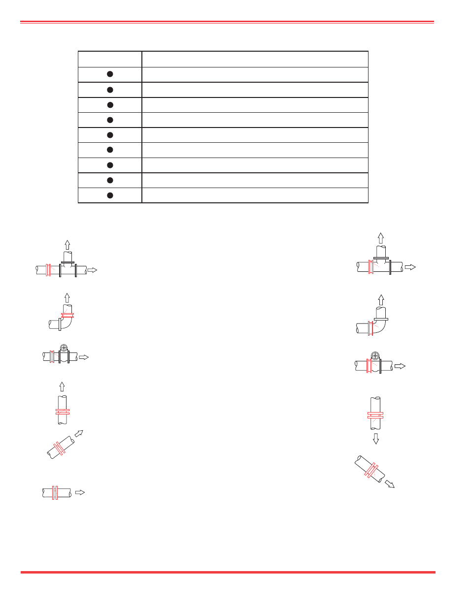
NORMAL FLOW
NORMAL FLOW
NORMAL FLOW
Note Hinge
Position
NORMAL FLOW
Note Hinge
Position
NORMAL FLOW
NORMAL FLOW
NORMAL FLOW
NORMAL
FLOW
Note Hinge
Position
Typical Applications with
Correct Valve Location
Avoid These Applications
with Incorrect Valve
Location
Feature
1.
Lowest initial cost
2.
Shortest lay length
3.
Lowest head loss (see head loss curves
4.
Resilient seat (standard)
5.
For waste and raw sewage
6.
For Clean water
7.
Buried service
8.
Vertical installation flow up only
9.
Flow Velocities up to 25 FPS
Recommendations for Installation Position
1. Install the valve in horizontal or upward flow for proper valve closure.
Caution: Do not use with reciprocating compressors, or in other pulsating
services.
Note:
Allow minimum (2) pipe diameters clearance downstream of check
valve with disc open to promote smooth flow.
INSTALLATION
Wafer style check valves are designed to fit between ANSI Class 125 and
Class 150 flat faced flanges. Two standard flange gaskets are recommend-
ed when installing 2” - 12” 501A valves. 14” and larger 501A valves do not
require gaskets. Determine minimum bolt or stud length by adding check
valve length to ANSI bolt or stud length.
Check Valve Length is Dimension B for 2” - 12” and Dimension D for 14” -
30” valves. ANSI bolt or stud length can be found in the following stan-
dards: For Class 125 use AWWA/ANSI standard B16.1. For Class 150 use
AWWA/ANSI standard B 16.5.