Series 501a - wafer swing check valves, Compact) 14" - 30, Dimensions – Cla-Val 501A Series User Manual
Page 3
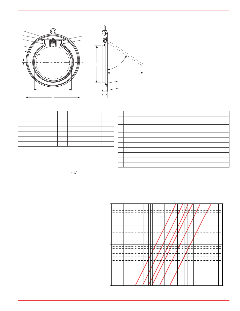
Series 501A - Wafer Swing Check Valves
(Compact) 14" - 30"
Dimensions
(Inches)
5 0 1 A P r e s s u r e D r o p v s F l o w R a t e
Features
•
The compact wafer thin body
provides extreme low weight.
•
Minimum width of body
allows installation between
various flange standards.
•
Seating O-Ring placed in
groove on body and is
easily replaceable.
•
Low pressure shut-off, even at
very low differential pressure;
due to disc rotational axis
location; which fully closes the
valve.
Size
A
B
C
D
E
(Deg.)
Q
W
Wt.Lbs.
14
10
1
⁄
2
17
1
⁄
2
11
1
⁄
2
1
1
⁄
2
56
10
5
⁄
8
40
16
12
20
1
⁄
2
13
1
⁄
4
2
56
11
1
⁄
2
13
⁄
32
58
18
14
21
1
⁄
2
15
2
52
12
1
⁄
2
13
⁄
32
69
20
16
23
3
⁄
4
17
2
1
⁄
3
49
13
1
⁄
2
11
⁄
16
110
24
19
28
1
⁄
2
20
1
⁄
2
3
47
15
3
⁄
4
11
⁄
16
162
30
25
35
26
1
⁄
2
3
44
19
1
⁄
2
11
⁄
16
290
No.
Description
Material
Specifications
1 Body*
Carbon Steel
(Electro-Galvanished Plated) AS1204 Grade 250
2 Disc*
Carbon Steel
(Electro-Galvanished Plated) AS1204 Grade 250
3 Shaft
316 Stainless Steel
ASTM A276 UNS S31600
4 Pivot Block
304 Stainless Steel
ASTM A276 UNS S31600
5 Washer
316 Stainless Steel
AISI 316 Stainless Steel
6 Cap screws
316 Stainless Steel
AISI 316 Stainless Steel
7 Seat O-Ring
Buna-N
®
(Standard)
Viton
TM
(Optional)
8 Spring
316 Stainless Steel
ASTM A316
9 Flange O-Ring # Buna-N
®
(Standard)
Viton
TM
(Optional)
Wafer style large diameter
swing check valves for
installations in minimum
space situations.
Note: *
Other Materials Available.
# Denotes flange O-Ring material is matched to Seat O-Ring
Note: Valves 14” - 30” have integral O-Ring
flange Seals, Gaskets are not required for
installation and should not be used.
Technical Data
Sizes:
14” - 30”
Pressure Rating:
235 psi
Temperature Range:
5º to 210º F
Buna-N
®
: -18ºC - 100ºC
Viton
TM
: -20ºC - 190ºC
Flange Type: ANSI 150 (flat faced)
General Application
A valve for wastewater, fire protection systems,
municipal water systems, natural gas systems
and HVAC Systems.
14”
(350mm)
16”
(400mm)
18”
(450mm)
20”
(500mm)
24”
(600mm)
30”
(750mm)
100
10
1
1000
1000
10000
Flow (gpm)
Pressure Drop
(Ft of W
ater)
2000
5000
2
5
50000
3
6
8
5
4
1
2
EyeBolt
W
C
B
D
7
9
A
Q
E
Note: Dimensions E & Q are only
relevant for Sch. 40 pipe. Consult
factory for other pipe I.D.
Note:
Q = Is the maximum dimension the disc extends from the
face of the valve
Kv = The flow rate of water in gpm that passes through
a valve with a pressure drop of 1 bar (14.5 psi) @68
º
F.
Kv = Cv /1.168
Dimensions are moninal in
W = Is the offset between the disc centerline and the valve
centerline.