Cla-val, Pilot system specifications, When ordering, please specify – Cla-Val 210-27/610-27 User Manual
Page 4
CLA-VAL
Copyright Cla-Val 2013 Printed in USA Specifications subject to change without notice.
P.O. Box 1325
• Newport Beach, CA 92659-0325 • Phone: 949-722-4800 • Fax: 949-548-5441 • E-mail: [email protected] • Website cla-val.com
©
Materials
Standard Pilot System Materials
Pilot Control: Bronze ASTM B62
Trim: Stainless Steel Type 303
Rubber: Buna-N
®
Synthetic Rubber
Optional Pilot System Materials
Pilot Systems are available with optional
Aluminum, Stainless Steel, or Monel
materials.
Valve position indicator is standard.
Pilot System Specifications
E-210-27/610-27 (R-5/2013)
CDS6A
Adjustment Ranges
5 - 40 ft.
30 - 80 ft.
70 - 120 ft.
110 - 160 ft.
150 - 200 ft.
Temperature Range
Water: to 180°F
If flowing line pressure is less than
10 psi, consult factory for full details. If inlet pressure
is above 150 psi, consult factory for
recommendations.
Fluids
Air, water, light oils
Rubber Parts:
Buna-N
®
Synthetic Rubber
Solenoid Control
Body:
Brass ASTM B283
Enclosure:
NEMA Type 1,2,3,3S,4,4
X
general purpose
watertight*
NEMA Type 6,6P,7,9 watertight Explosion
Proof available.
Voltages:
110, 220 - 50Hz AC
24, 120, 240, 480 - 60Hz AC
6, 12, 24, 120, 240 - DC
Others available.
Max. operating pressure differential:
200 psi*
Coil:
Insulation molded Class
F
Watts AC
6
AC Volt Amps Inrush
30
AC Volt Amps Holding
16
Watts DC
10.6
Manual operator available.
*Supplied unless otherwise specified
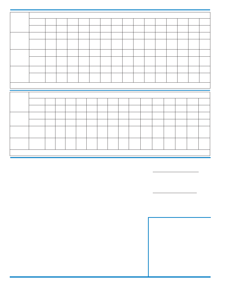
210-27
Valve
Selection
100-01 Pattern:
Globe (G), Angle (A),
End Connections:
Threaded (T), Grooved (GR), Flanged (F) Indicate Available Sizes
Inches
2
2
1
⁄
2
3
4
6
8
10
12
14
16
18
20
24
30
36
mm
50
65
80
100
150
200
250
300
350
400
450
500
600
750
900
Basic Valve
100-01
Pattern
G, A
G, A
G, A
G, A
G, A
G, A
G, A
G, A
G, A
G, A
G
G
G, A
G
G
End Detail
T, F,
Gr
T, F,
Gr*
T, F,
Gr
F,
Gr
F,
Gr*
F,
Gr*
F
F
F
F
F
F
F
F
F
Suggested
Flow
(gpm)
Maximum
210
300
460
800
1800
3100
4900
7000
8400
11000
14000
17000
25000
42000
50000
Maximum
Intermittent
260
370
580
990
2250
3900
6150
8720
10540
13700
17500
21700
31300
48000
62500
Suggested
Flow
(Liters/Sec)
Maximum
13
19
29
50
113
195
309
442
530
694
883
1073
1577
2650
3150
Maximum
Intermittent
16
23
37
62
142
246
387
549
664
863
1104
1369
1972
3028
3940
100-01 Series is the full internal port Hytrol.
*
Globe Grooved Only
610-27
Valve
Selection
100-20 Pattern:
Globe (G), Angle (A),
End Connections:
Flanged (F) Indicate Available Sizes
Inches
3
4
6
8
10
12
14
16
18
20
24
30
36
42
48
mm
80
100
150
200
250
300
350
400
450
500
600
750
900
1000
1200
Basic Valve
100-20
Pattern
G
G, A
G, A
G, A
G
G
G
G
G
G
G
G
G
G
G
End Detail
F
F
F
F
F
F
F
F
F
F
F
F
F
F
F
Suggested
Flow
(gpm)
Maximum
260
580
1025
2300
4100
6400
9230
9230
16500
16500
16500
28000
33500
33500
33500
Suggested
Flow
(Liters/Sec)
Maximum
16
37
65
145
258
403
581
581
1040
1040
1040
1764
2115
2115
2115
100-20 Series is the reduced internal port size version of the 100-01 Series.
When Ordering, Please Specify
1. Catalog No. 210-27 or No. 610-27
2. Valve Size
3. Pattern - Globe or Angle
4. Pressure Class
5. Threaded or Flanged
6. Materials Desired
7. Engineered or de-engineered to open
Main Valve
8. Solenoid Enclosure, Voltage & Hertz,
Coil Insulation and Max. Operating
Pressure Differential
9. Adjustment Range
10. Desired Options
11. When Vertically Installed