Cf1-c1, Float control, Cla-val – Cla-Val 124-02/624-02 Technical Manual User Manual
Page 20: When ordering parts, please specify, Parts list
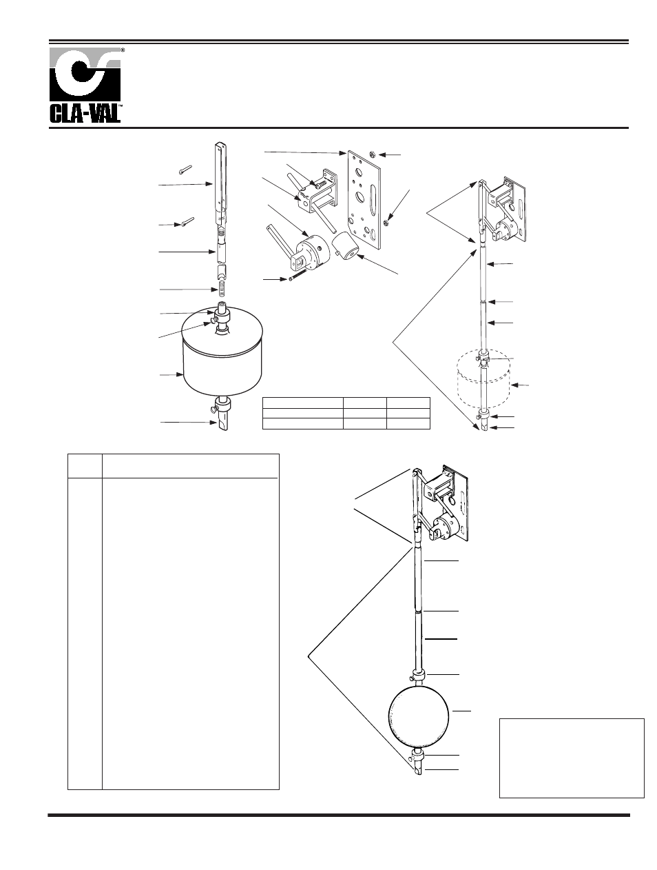
When ordering parts,
please specify:
• All nameplate data
• Description
• Item Number
ITEM
DESCRIPTION
1
Link Assembly
2
Cotter Pins (2 req'd)
3
Float Rod Assembly (2 ft. )
FLOAT ROD ASSY. BREAKDOWN ITEMS 4 - 9
4
Upper Float Rod (1 ft.)
Upper Float Rod (2 ft.)
5
Stud (Req. for connecting upper and lower rods
and one for each extension rod)
6
Extension Float Rod (1 ft.)
Extension Float Rod (2 ft.)
7
Stop Collar (2 req'd)
8
Set Screw (1 ea. stop collar)
9
Lower Float Rod (1 ft.)
Lower Float Rod (2 ft.)
10
Float Ball (Standard Plastic)
10 SS
Float Ball (Optional Stainless Steel)
11
Base and Mounting Plate
12
Pilot Valve Assembly CF1-Cl
13
Machine Screw 6/32 x 1 1/2" (6 req'd.)
14
Hex Nut 6/32 (6 req)
15
Counter Balance Bracket Assy.
16
Machine Screw 10/32 x 9/16" (4 req'd.)
17
Hex Nut 10/32 (4 req'd.)
18
Counterweight (varies with rod
length, includes set screw)
19
Pilot & Bracket Assembly CF1-Cl
COUNTERWEIGHT NOT INCLUDED
13
18
12
11
15
16
17
14
19
7
9
9
10
8
7
5
10
8
6
3
FLOAT
ROD
ASSEMBLY
PILOT &
BRACKET
ASSEMBLY
COUNTERWEIGHT
NOT INCLUDED
4
2
1
4
5
OPERATION
FLOAT POSITION
PORT 1
PORT 2
Up
Pressure
Drain
Down
Drain
Pressure
Float Control
CF1-C1
19
4
5
6
8
3
Float
Rod
Assembly
Pilot &
Bracket
Assembly
7
9
10 SS
Optional Stainless Steel Float
CLA-VAL
Copyright Cla-Val 2009 Printed in USA Specifications subject to change without notice.
P.O. Box 1325
• Newport Beach, CA 92659-0325 • Phone: 949-722-4800 • Fax: 949-548-5441 • E-mail: [email protected] • Website cla-val.com
©
N- CF1-C1 (R-4/09)
PARTS LIST
NOTE:
A stilling well (Min. 8"
I.D.) must be provided
around the float if the
liquid surface is subject
to turbulence, ripples
or wind.