Cf1 series, Cf1 series float controls – Cla-Val 124-02/624-02 Technical Manual User Manual
Page 19
CF1 Series Float Controls
CF1 Series
INSTALLATION / OPERATION / MAINTENANCE
Initial Adjustment CF1 Series Float Controls
Check installation to be sure that liquid surface is not subject to wind or currents, if so, a stilling well should be
installed around the float and rod assembly. A short section of 8" pipe (PVC) mounted vertically in the tank
around the float and rod is suggested.
1. See parts sheet (other side of this sheet) for proper assembly of the float rod, float, and stop collars and for
threading into the Link Assembly of the CF1-C1.
2. Balance the Float Rod Assembly. This compensates for the buoyancy of the float rod in the water.
Temporarily remove float by removing float rod and float from the link assembly. Remove float from float rod,
reinstall rod assembly (leave stop collars on float rod) back into link assembly.
Adjust counterweight on rod to balance the weight of the float rod assembly less the float. Loosen setscrew on
counterweight and move weight in or out round rod remains horizontal without shifting. Tighten setscrew.
Check by pushing up or down on float rod assembly and seeing that entire assembly returns to balanced posi-
tion. Replace float between the stop collars. The counterweight size changes as float rod is lengthened.
Consult factory for more information.
3. Set Float High Level Shut-Off. Move float rod to "up" position. Adjust the upper stop collar on the float rod
assembly approximately three inches above the desire high water level. Move float rod to "down" position.
Adjust the lower stop collar on the float rod assembly approximately three inches below the desired low water
level. Tighten collar set screws.
4. If the closing level is too high, allowing tank to overflow, then the top stop collar on the float rod should be
lowered. If the opening level is too low, then the bottom stop collar should be raised.
If the counterweight has been properly adjusted the float will move freely on the float rod, without causing the
pilot arm to raise or lower, until the float actually contacts one of the stop collars.
5. For reference: with a new control and supply pressure less than 40 psi the maximum level differential avail-
able will be: 18 to 20 inches with PVC float and rod assembly and 48 to 50 inches with Stainless Steel or Brass
float and rod assembly.
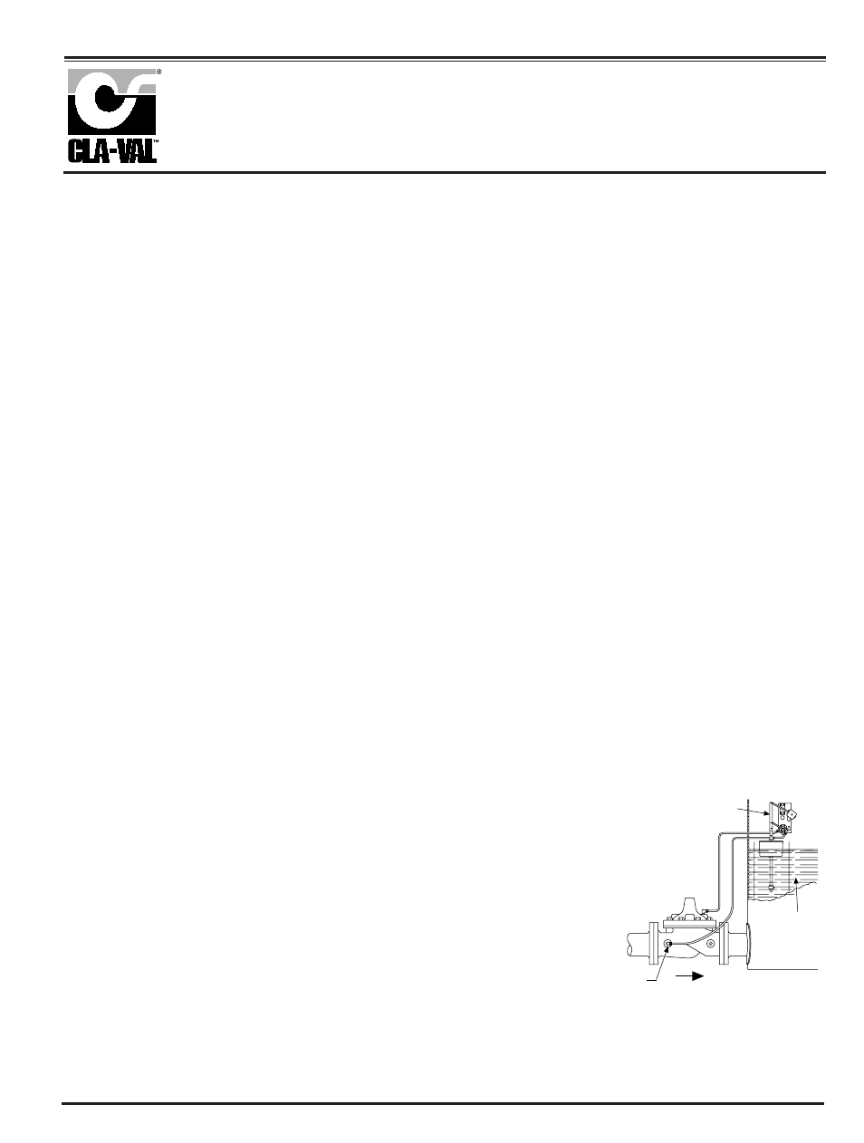
Installation Data
The float control is mounted above the
high water level in the tank. The valve is
installed in the line leading to the tank
and is connected to the float control
pilot by tubing. (Min. 3/8" tubing)
When line pressure is used to operate
the valve, tubing connections are made
from the float control pilot to the valve
cover, and also to the inlet side of the
valve. An X43 “Y” Strainer or X46 Flow
Clean Strainer must be installed in the
inlet side of the valve. The control may
be installed at any elevation above the
valve, providing that the flowing line
pressure in psi is equal to, or greater
than, the vertical distance in feet
between the valve and the float control.
An independent source of air or water
may be used to operate the valve. The
pressure from this independent source
must constantly be equal to or greater
than pressure at the valve inlet. The
independent source is connected to the
float control pilot in place of the supply
line connected to the inlet side of the
valve. If the Model 100-01 under the
control of the CF1-C1 is 8" or larger,
auxiliary Hytrols may be required.
Consult factory for details.
NOTE:
A stilling well (Min. 8" I.D.) must be pro-
vided around the float if the liquid surface
is subject to turbulence, ripples or wind.
Stilling
Well
Flow
CF1-C1
X43 or
X46
Strainer
Note: We recommend protecting Float Control tubing and valve from freezing temperatures.