Pressure ratings, Specifications, Materials – Cla-Val 50-01KO/650-01KO User Manual
Page 8
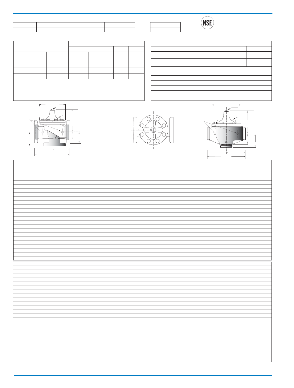
Cla-Val Control Valves with KO ANTI-CAVITATION Trim operate with maximum efficiency when mounted in horizontal piping with the main valve cover Up. We recommend isolation valves
be installed on inlet and outlet for maintenance. Adequate space above and around the valve for service personnel should be considered essential. A regular maintenance program should
be established based on the specific application data. However, we recommend a thorough inspection be done at least once a year. Consult factory for specific recommendations.
GGGG
DDDD
Inlet
AAAA
100-01KO
Grooved
EE
CC
(MAX)
K
J
H
Inlet
Outlet
B
(Diameter)
G
GG
GGG
D
Inlet
DD
DDD
F
FF
100-01KO
Threaded &
Flanged
A
E
C
(MAX)
K
J
H
Inlet
Outlet
AA
AAA
B
(Diameter)
Pressure Ratings
(Recommended Maximum Pressure - psi)
Model 100-01KO
G
GG
GGG
D
Inlet
DD
DDD
F
FF
100-01KO
Threaded &
Flanged
A
E
C
(MAX)
K
J
H
Inlet
Outlet
AA
AAA
B
(Diameter)
Specifications
Operating Temp. Range
Pattern
Globe
Angle
Grooved End
Size
1-
1
⁄
4
" - 36"
1-
1
⁄
4
" - 16" & 24"
1-
1
⁄
2
" - 8"
APPROVED
(4" - 24")
Component
Standard Material Combinations
Body & Cover
Ductile Iron
Cast Steel
Bronze
Available Sizes
1-1/4" - 36"
3" - 16"
3" 16"
Disc Retainer &
Diaphragm Washer
Cast Iron
Cast Steel
Bronze
Trim: Disc Guide,
Seat & Cover Bearing
Stainless Steel is Standard
Disc
Buna-N
®
Rubber
Diaphragm
Nylon Reinforced Buna-N
®
Rubber
Stem, Nut & Spring
Stainless Steel
For material options not listed consult factory.
Cla-Val manufactures valves in more than 50 different alloys.
Materials
Note:
Consult Factory
on 10",12", 16"
angle pattern
Valve Body & Cover
Pressure Class
Flanged
Grooved Threaded
Grade
Material
ANSI
Standards*
150
Class
300
Class
300
Class
End‡
Details
ASTM A536
Ductile Iron B16.42
250
400
400
400
ASTM A216-WCB Cast Steel
B16.5
285
400
400
400
ASTM B62
Bronze
B16.24
225
400
400
400
Note:
* ANSI standards are for flange dimensions only.
Flanged valves are available faced but not drilled.
‡ End Details machined to ANSI B2.1 specifications.
Valves for higher pressure are available; consult factory for details
Valve Size
(Inches)
1
1/4
1
1/2
2
2
1/2
3
4
6
8
10
12
14
16
18
20
24
30
36
A Threaded
7.25
7.25
9.38
11.00 12.50
—
—
—
—
—
—
—
—
—
—
—
—
AA 150 ANSI
—
8.50
9.38
11.00 12.00 15.00 20.00 25.38 29.75 34.00 39.00 41.38 46.00 52.00 61.50 63.00 76.00
AAA 300 ANSI
—
9.00 10.00 11.62 13.25 15.62 21.00 26.38 31.12 35.50 40.50 43.50 47.64 53.62 63.24 64.50 76.00
AAAA Grooved End
—
8.50
9.00
11.00 12.50 15.00 20.00 25.38
—
—
—
—
—
—
—
—
—
B Dia.
5.62
5.62
6.62
8.00
9.12
11.50 15.75 20.00 23.62 28.00 32.75 35.50 41.50 45.00 53.16 56.00 66.00
C Max.
5.50
5.50
6.50
7.56
8.19
10.62 13.38 16.00 17.12 20.88 24.19 25.00 39.06 41.90 43.93 54.60 61.50
CC Max. Grooved End
—
4.75
5.75
6.88
7.25
9.31
12.12 14.62
—
—
—
—
—
—
—
—
—
D Threaded
3.25
3.25
4.75
5.50
6.25
—
—
—
—
—
—
—
—
—
—
—
—
DD 150 ANSI
—
4.00
4.75
5.50
6.00
7.50
10.00 12.69 14.88 17.00 19.50 20.81
—
—
30.75
—
—
DDD 300 ANSI
—
4.25
5.00
5.88
6.38
7.88
10.50 13.25 15.56 17.75 20.25 21.62
—
—
31.62
—
—
DDDD Grooved End
—
—
4.75
—
6.00
7.50
—
—
—
—
—
—
—
—
—
—
—
E
1.12
1.12
1.50
1.69
2.06
3.19
4.31
5.31
9.25
10.75 12.62 15.50 12.95 15.00 17.75 21.31 24.56
EE Grooved End
—
2.00
2.50
2.88
3.12
4.25
6.00
7.56
—
—
—
—
—
—
—
—
—
F 150 ANSI
—
2.50
3.00
3.50
3.75
4.50
5.50
6.75
8.00
9.50
10.50 11.75 15.00 16.50 19.25 22.50 25.60
FF 300 ANSI
—
3.06
3.25
3.75
4.13
5.00
6.25
7.50
8.75
10.25 11.50 12.75 15.00 16.50 19.25 24.00 25.60
G Threaded
1.88
1.88
3.25
4.00
4.50
—
—
—
—
—
—
—
—
—
—
—
—
GG 150 ANSI
—
4.00
3.25
4.00
4.00
5.00
6.00
8.00
8.62
13.75 14.88 15.69
—
—
22.06
—
—
GGG 300 ANSI
—
4.25
3.50
4.31
4.38
5.31
6.50
8.50
9.31
14.50 15.62 16.50
—
—
31.62
—
—
GGGG Grooved End
—
—
3.25
—
4.25
5.00
—
—
—
—
—
—
—
—
—
—
—
H NPT Body Tapping
.375
.375
.375
.50
.50
.75
.75
1
1
1
1
1
1
1
1
2
2
J NPT Cover Center Plug
.25
.25
.50
.50
.50
.75
.75
1
1
1.25
1.5
2
1.5
1.5
1.5
2
2
K NPT Cover Tapping
.375
.375
.375
.50
.50
.75
.75
1
1
1
1
1
1
1
1
2
2
Stem Travel
0.4
0.4
0.6
0.7
0.8
1.1
1.7
2.3
2.8
3.4
4.0
4.5
5.1
5.63
6.75
7.5
8.5
Approx. Ship Wt. Lbs.
15
15
35
50
70
140
285
500
780
1165
1600
2265
2982
3900
6200
7703 11720
Fluids
-40 to 180 F
Valve Size
(mm)
32
40
50
65
80
100
150
200
250
300
350
400
450
500
600
750
900
A Threaded
184
184
238
279
318
—
—
—
—
—
—
—
—
—
—
—
—
AA 150 ANSI
—
216
238
279
305
381
508
645
756
864
991
1051
1168
1321
1562
1600
1930
AAA 300 ANSI
—
229
254
295
337
397
533
670
790
902
1029
1105
1210
1362
1606
1638
1930
AAAA Grooved End
—
216
228
279
318
381
508
645
—
—
—
—
—
—
—
—
—
B Dia.
143
143
168
203
232
292
400
508
600
711
832
902
1054
1143
1350
1422
1676
C Max.
140
140
165
192
208
270
340
406
435
530
614
635
992
1064
1116
1387
1562
CC Max. Grooved End
120
120
146
175
184
236
308
371
—
—
—
—
—
—
—
—
—
D Threaded
83
83
121
140
159
—
—
—
—
—
—
—
—
—
—
—
—
DD 150 ANSI
—
102
121
140
152
191
254
322
378
432
495
528
—
—
781
—
—
DDD 300 ANSI
—
108
127
149
162
200
267
337
395
451
514
549
—
—
803
—
—
DDDD Grooved End
—
—
121
—
152
191
—
—
—
—
—
—
—
—
—
—
—
E
29
29
38
43
52
81
110
135
235
273
321
394
329
381
451
541
624
EE Grooved End
—
52
64
73
79
108
152
192
—
—
—
—
—
—
—
—
—
F 150 ANSI
—
64
76
89
95
114
140
171
203
241
267
298
381
419
489
572
650
FF 300 ANSI
—
78
83
95
105
127
159
191
222
260
292
324
381
419
489
610
650
G Threaded
48
48
83
102
114
—
—
—
—
—
—
—
—
—
—
—
—
GG 150 ANSI
—
102*
83
102
102
127
152
203
219
349
378
399
—
—
560
—
—
GGG 300 ANSI
—
102*
89
110
111
135
165
216
236
368
397
419
—
—
582
—
—
GGGG Grooved End
—
—
83
—
108
127
—
—
—
—
—
—
—
—
—
—
—
H NPT Body Tapping
.375
.375
.375
.50
.50
.75
.75
1
1
1
1
1
1
1
1
2
2
J NPT Cover Center Plug
.25
.25
.50
.50
.50
.75
.75
1
1
1.25
1.5
2
1.5
1.5
1.5
2
2
K NPT Cover Tapping
.375
.375
.375
.50
.50
.75
.75
1
1
1
1
1
1
1
1
2
2
Stem Travel
10
10
15
18
20
28
43
58
71
86
102
114
130
143
171
190
216
Approx. Ship Wt. Kgs.
7
7
16
23
32
64
129
227
354
528
726
1027
1353
1769
2812
3494
5316