E-90-72_4, Cla-val, When ordering, please specify – Cla-Val 90-72/690-72 User Manual
Page 4: Pilot system specifications
Materials
Standard Pilot System Materials
Pilot Control: Bronze ASTM B62
Trim: Stainless Steel Type 303
Rubber: Buna-N
®
Synthetic Rubber
Optional Pilot System Materials
Pilot Systems are available with optional
Aluminum, Stainless Steel or Monel
materials.
When Ordering, Please
Specify
1. Catalog No. 90-72 or No. 690-72
2. Valve Size
3. Pattern - Globe or Angle
4. Pressure Class
5. Threaded or Flanged
6. Trim Material
7. Adjustment Range
8. Desired Options
9. When Vertically Installed
10. Product Enhancement
Pilot System Specifications
PO Box 1325 Newport Beach CA 92659-0325
Phone: 949-722-4800
Fax: 949-548-5441
CLA-VAL
CLA-VAL CANADA
CLA-VAL EUROPE
4687 Christie Drive
Beamsville, Ontario
Canada L0R 1B4
Phone: 905-563-4963
Fax: 905-563-4040
Chemin dés Mesanges 1
CH-1032 Romanel/
Lausanne, Switzerland
Phone: 41-21-643-15-55
Fax: 41-21-643-15-50
©
COPYRIGHT CLA-VAL 2013 Printed in USA
Specifications subject to change without notice.
www.cla-val.com
E-90-72/690-72 (09/2013)
Represented By:
Adjustment Ranges
CRD
2 to
30 psi
15 to
75 psi
20 to 105 psi
30 to 300 psi
Model 990 (Bypass)
7 to 29 psi
29 to 87 psi
87 to 145 psi
Temperature Range
Water: to 180°
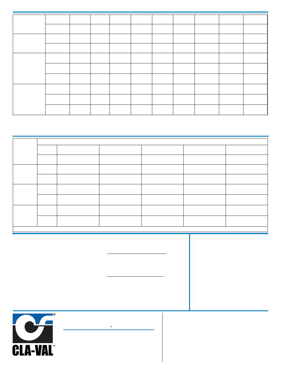
90-72
Valve
Selection
Inches
1
1
1
⁄
4
1
1
⁄
2
2
2
1
⁄
2
3
4
6
8
mm
25
32
40
50
65
80
100
150
200
Basic Valve
100-01
Pattern
G, A
G, A
G, A
G, A
G, A
G, A
G, A
G, A
G, A
End Detail
T
T
T, F,
Gr*
T, F,
Gr
T, F,
Gr*
T, F,
Gr
F,
Gr
F,
Gr*
F,
Gr*
Suggested
Flow
(gpm)
Maximum
55
93
125
210
300
460
800
1800
3100
Maximum
Intermittent
68
120
160
260
370
580
990
2250
3900
Minimum
1
1
1
1
1
1
1
1
1
Suggested
Flow
(Liters/Sec)
Maximum
3.5
6
8
13
19
29
50
113
195
Maximum
Intermittent
4.3
7.6
10
16
23
37
62
142
246
Minimum
.03
.03
.03
.06
.06
.06
.06
.06
0.95
690-72
Valve
Selection
100-20 Pattern:
Globe (G), Angle (A),
End Connections:
Flanged (F) Indicate Available Sizes
Inches
3
4
6
8
10
mm
80
100
150
200
250
Basic Valve
100-20
Pattern
G
G, A
G, A
G, A
G
End Detail
F
F
F
F
F
Suggested
Flow
(gpm)
Maximum
260
580
1025
2300
4100
Minimum
1
1
1
1
1
Suggested
Flow
(Liters/Sec)
Maximum
16
37
65
145
258
Minimum
.06
.06
.06
.06
.95
100-20 Series is the reduced internal port size version of the 100-01 Series. For Lower Flows Consult Factory
100-01 Pattern:
Globe (G), Angle (A),
End Connections:
Threaded (T), Grooved (GR), Flanged (F) Indicate Available Sizes
100-01 Series is the full internal port Hytrol.
For Lower Flows Consult Factory
*
Globe Grooved Only