Cla-Val 133VF User Manual
Page 3
8” valve flow rate
RTU
Not Supplied by
CLA-VAL
Power
Supply
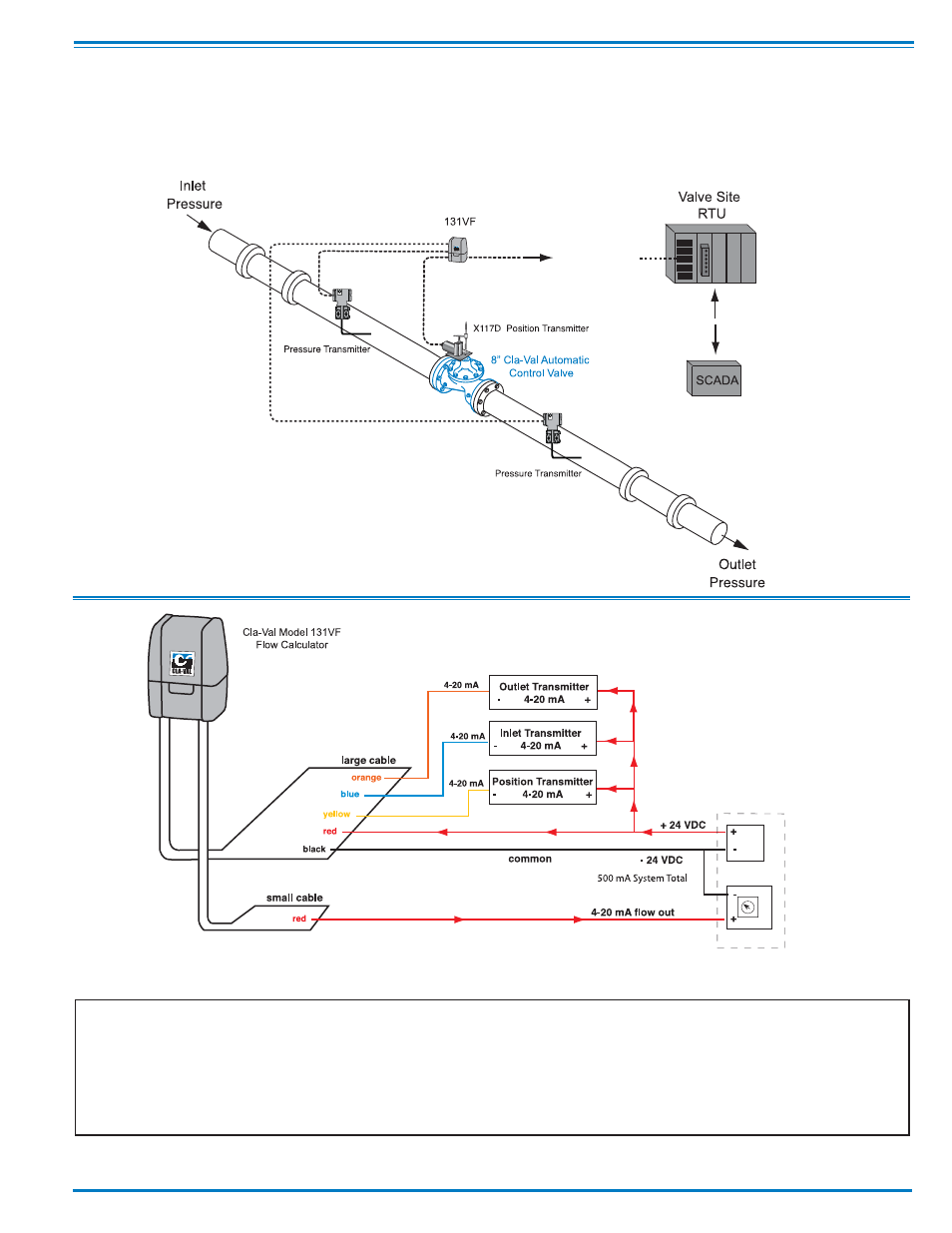
133VF System Using Inlet & Outlet Pressure Sensing
Wiring Diagram
Typical 133VF System installation where two pressure transmitters are used upstream and downstream of the
valve. The 131VF module will calculate pressure differential from these two sensors. When inlet and outlet
pressure values are to be sent to RTU, then loop isolators should be installed on the 4 - 20 mA signals going to
SCADA and the 131VF. Provide for adequate protection from lightning strikes.
Use loop powered isolators when sending
4-20 mA pressure signals to SCADA.
Visit www.cla-val.com to learn more about Cla-Val’s extensive line
of electronic control valves and ancillary products.
other wires not used
See also other documents in the category Cla-Val Equipment:
- 136-01/636-01 Solenoid Control Valve Quick Manual (2 pages)
- 136-03/636-03 Valve Quick Manual (2 pages)
- 136-01/636-01 Technical Manual (36 pages)
- 136-03/636-03 Technical Manual (36 pages)
- X52E Orifice Plate Assembly (4 pages)
- 49-01/649-01 Quick Manual (2 pages)
- 49-01/649-01 Technical Manual (33 pages)
- 40-01/640-01 Quick Manual (2 pages)
- 40-01/640-01 Technical Manual (28 pages)
- 90-01/690-01 Quick Manual (2 pages)
- 90-01/690-01 Technical Manual (29 pages)
- 90-48/690-48 Quick Manual (2 pages)
- 90-48/690-48 Technical Manual (34 pages)
- 92-01/692-01 Quick Manual (2 pages)
- 92-01/692-01 Technical Manual (28 pages)
- 93-01/693-01 Quick Manual (2 pages)
- 93-01/693-01 Technical Manual (42 pages)
- 590-01/6590-01 Quick Manual (2 pages)
- 590-01/6590-01 Technical Manual (21 pages)
- 60-11/660-11 Quick Manual (1 page)
- 60-11/660-11 Technical Manual (27 pages)
- 61-02/661-02 Technical Manual (34 pages)
- 60-73/660-73 Technical Manual (36 pages)
- 581 Series Quick Manual (2 pages)
- 581 Series Technical Manual (7 pages)
- 81-02/681-02 Quick Manual (2 pages)
- 81-02/681-02 Technical Manual (24 pages)
- 81-01/681-01 Quick Manual (2 pages)
- 81-01/681-01 Technical Manual (24 pages)
- 98-06/698-06 Quick Manual (4 pages)
- 98-06/698-06 Technical Manual (36 pages)
- 43-01/643-01 (35 pages)
- 390-07/3690-07 (40 pages)
- 585 Series (4 pages)
- 584 (2 pages)
- 501A Series (2 pages)
- 501A Series (4 pages)
- 583 (1 page)
- 81-12 (2 pages)
- 582 Series (4 pages)
- 38VB/AR Series (4 pages)
- PC-1 (8 pages)
- 60-32/660-32 (4 pages)
- 60-31/660-31 (4 pages)
- 61-02KO/661-02KO Valve (4 pages)