Cla-Val 34AR Series User Manual
Page 4
REASSEMBLY
Clean all parts and gaskets surfaces with a wire brush in the
direction of the serrations or machine marks. Replace worn
parts, gaskets and seals before reassembly. Refer to Figure 2.
1. Apply Loctite PST No. 565 thread sealant to seat (4) and
screw into cover with maximum torque of 20 ft-lbs;
DO NOT OVER-TORQUE.
2. Screw down lever frame (3) to cover, over locating pin (21)
in cover, with screws (8) and washers (30).
3. Install new orifice button (11) flush to arm (22). Assemble
lockwasher (34) and locknut (18) over orifice button but do
not tighten. (see 5)
4. Connect arms (10 & 22) and assemble to lever frame (3) with
four pivot pins (12) and retaining rings (13); rings should
snap over pins.
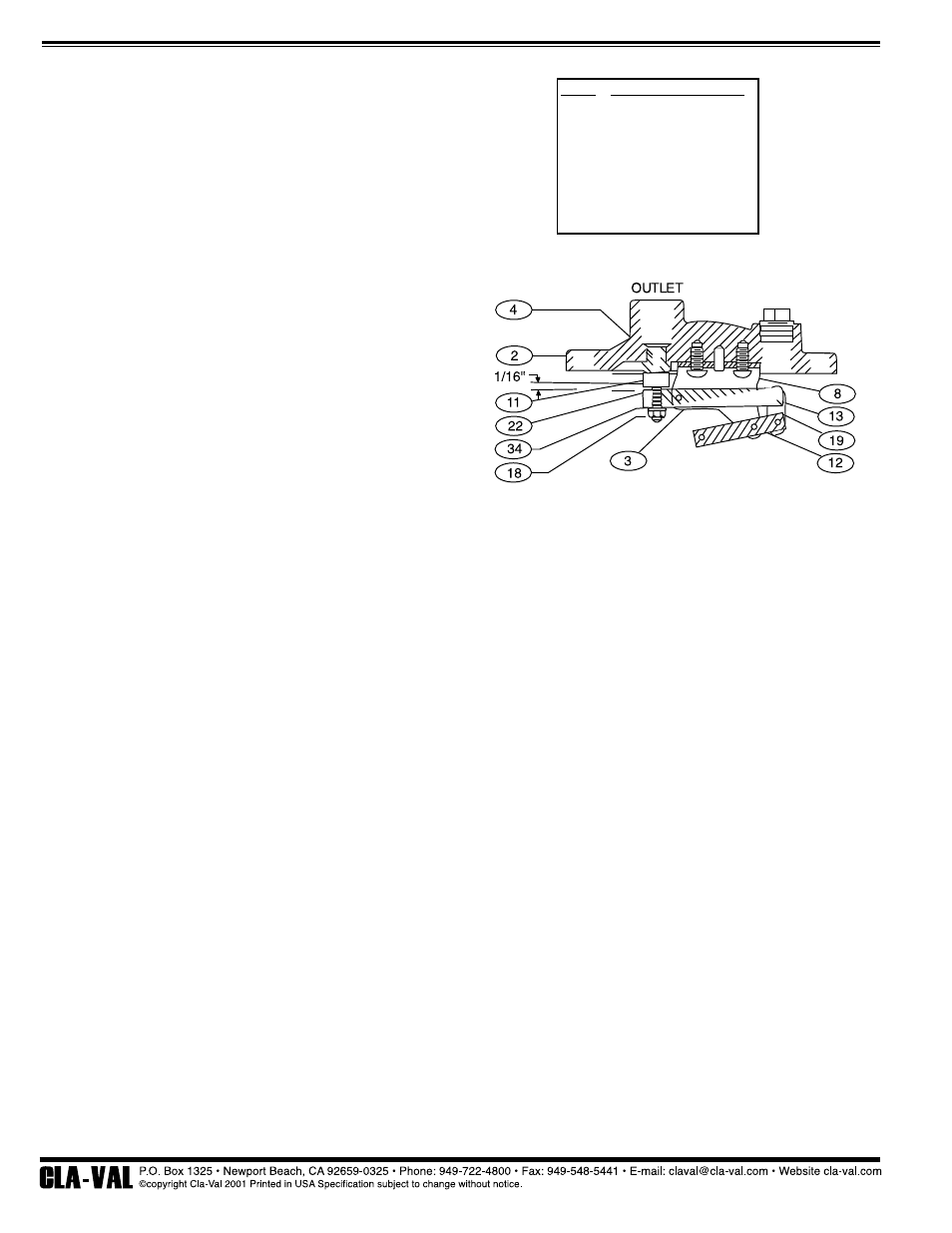
5. Adjust orifice button (11) so that orifice button arm (22)
slopes up about 1/16” when resting gently against seat (4) as
shown in Figure 4. Secure button by tightening lockwasher
(34) and nut (18).
6. Attach float (5) by installing last pivot pin (12) into lever frame
(3). Float should lift freely pressing the orifice button (11)
against the seat (4) when pushed upward. Verify that all
retainers rings (13) are properly secured.
7. Lay new cover gasket (6) on clean surface and apply a
gasket compound such as Garlock 101-S to both surfaces.
Assemble gasket (6) and cover (2) over bolt holes in body (1).
8. Lubricate bolts (7) and tighten to the torques in Table 2.
9. Install ARV back in service. Refer to installation instructions.
Slowly open inlet shut-off valve. Valve is now back in
operation mode.
For above parts description and recommended spare parts kit see page 2
PARTS AND SERVICE
Parts and service are available from Cla-Val agent or distributor
or the factory.
Note the ARV Model No. and Working Pressure are on the ARV
nameplate.
SIZE
1/4”
5/16”
3/8”
7/16”
1/2”
7/8”
TORQUE (FT-LBS)
6
11
19
30
45
202
N-Air Release Valve 34AR (R-11/01)
Figure 4. Compound Lever ARV mechanism
for Orifice Button Adjustment