Cla-Val 34AR Series User Manual
Page 3
MAINTENANCE
The simple and compound Air Release Valves (ARV)
require no regular lubrication or maintenance.
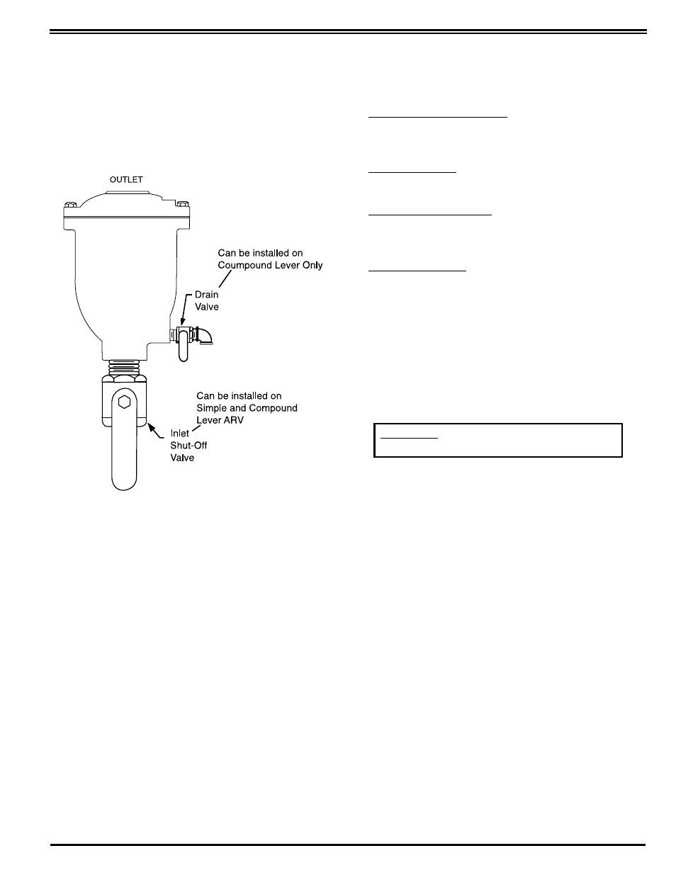
A Periodic inspection to verify operation can be performed.
A manual drain valve can be installed in place of the lower
drain plug (14 - Fig. 2) to perform this operation as shown in
Figure 3.
1. Partially open inlet shut off valve until water flow is
visible. This will indicate the ARV is working properly. If
only air flow observed is follow steps 2-6.
2. Close inlet shut-off valve.
3. Slowly open drain valve to allow fluid in ARV to drain. If
draining is difficult, the orifice may be clogged (valve
requires service).
4. Close drain valve.
5. Slowly crack open inlet shut-off valve to fill ARV with fluid.
Observe the seating action and verify that valve closes
without leakage.
6. If leakage occurs, remove ARV to inspect internals for
wear or damage from foreign objects.
PROBLEMS
Solutions, presented below, will assist you troubleshooting
the ARV assembly in an efficient manner.
•
Leakage at Inlet Connection: Tighten valve threaded
connection. If leaks persists, remove valve and seal
threads with pipe sealant.
•
Leakage at Cover: Tighten bolts per Table 2, or replace
cover gasket.
•
ARV Leaks when Closed: Flush ARV to remove debris.
Disassemble and inspect seat, orifice button, for damage
and float for water content.
•
ARV not Venting Air: Check that system operating
pressure does not exceed Working Pressure on ARV
nameplate. Inspection per steps 2-6 and disassemble
valve if problems persists.
DISASSEMBLY
Work on the ARV Should be one by a Qualified Mechanic
The ARV can be disassembled without removing it from the
pipeline. Or for the ARV can be removed from the line. No
special tools are required to make repairs.
1. Close inlet shut-off valve. Open drain valve or slowly remove
drain plug. Remove the cover bolts (7) from top cover
2. Pry cover (2) loose and lift off ARV body.
3. Remove the 2 retainer rings (13) and pivot pins (12) that
pass through the lever frame (3). The float (5) and linkage will
be free from the cover. Disconnect float from lever (10).
4. To remove lever frame (3), remove two rounded-head
fasteners (8). Rotate seat (4) counter-clockwise to remove.
5. Remove locknut (18) and orifice button (11) from orifice
button arm (22).
6. Clean and inspect parts. Note: some floats contain sand
for required weight; if water is detected, replace float.
Replace worn parts as necessary and lubricate parts with
food grade grease.
WARNING: The valve must be depressurized
before taking the cover off.
FIG. 3 INSPECTION