Cla-Val 36 Series User Manual
Page 5
MAINTENANCE: Arrestor checks require no schedule
maintenance. Flow thru this valve is adjustable. should the
float in the air valve slam shut due to the water flow, plug
up the tapped holes of the disc with standard fastener and
lockwashers until the desired non-slam is achieved.
DISASSEMBLY:
The arrestor check must be disconnected from the air
vacuum valve for disassembly
WARNING:
Drain the valve before unbolting the
flanged or internal pressure may cause injury.
1. Close main isolation valve. Drain air/vacuum valve
and remove from top of anti-slam valve. Replace
gasket if damaged.
2. Unbolt air/vacuum valve and remove from top of
anti-slam valve. Replace gasket if damaged.
3. Remove small seat fastener on flange face.
4. Lift seat, disc and spring from valve body. 14” and
larger valves do not have spring.
5. Clean and inspect parts for wear.
Replace parts if worn or damaged. During reassembled,
tighten flange bolts with the “Max. Torque” values given
in table 1.
PARTS AND SERVICE
Parts and service are available from your local repre-
sentative or the factory. Make note of the valve size and
model no. located on the valve nameplate and contact
CLA-VAL
A sales representative will quote prices for parts or
arrange for service as needed.
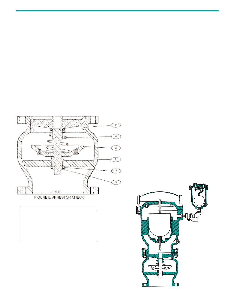
ITEM
1
2
3
4
5
6
7
DESCRIPTION
Body
Seat
Disc*
Spring (4” - 12”)
Bushing
Seat Ret. Screw*
Retainer Nut*
MATERIAL
Cast Iron
Bronze
Bronze
Stainless Steel
Brass
Stainless Steel
Brass
* Recommended Spare Part List
TABLE 4. ARRESTOR CHECK PARTS LIST
OPTIONAL ARRESTOR CHECK OPERATION
Air/Vacuum Valves may be factory or field equipped with
an arrestor check on the inlet port as shown in Figure 4.
The function of the arrestor check is to protect the air/vac-
uum valve from slam shock, resulting from instant pipeline
flow stoppage.
The arrestor check is normally open, allowing unrestricted
flow of air in and out of the air/vacuum valve. But, when
high velocity water enters the valve, the force raises the
disc to its closed position and the flow of water is throttled
through small ports in the disc to reduce shock closure and
water hammer.
The standard valve body material is cast iron with bronze
disc. General details of construction are illustrated in figure
5. The body (1) is flanged for connection to the pipeline.
See page 2 for installation to the pipeline.