Backflushing procedures, Series mtp 36ww-bw side mounted style, Series mtp 36ww-bw candelabra style – Cla-Val 34WW Series User Manual
Page 4: Air release valve, Air and vacuum valve, Ca a, Ab a b
5
17
20
10
13
12
19
14
30
6
14
8
21
4
7
2
11
22
34
18
3
33
35
1
5
14
1
5L
20
9
2
7
6
4
8
3
C
A
A
2"
SHUT OFF
VALVES
Quick Disconnect
Coupling Valve
E
Valve
D
B
B
4
7
26
2
9
28
8
5
5
1
27
15
28
27
6
9
28
5
17
20
10
13
12
19
14
30
6
14
8
21
4
7
2
11
22
34
18
3
33
35
1
A
B
A
B
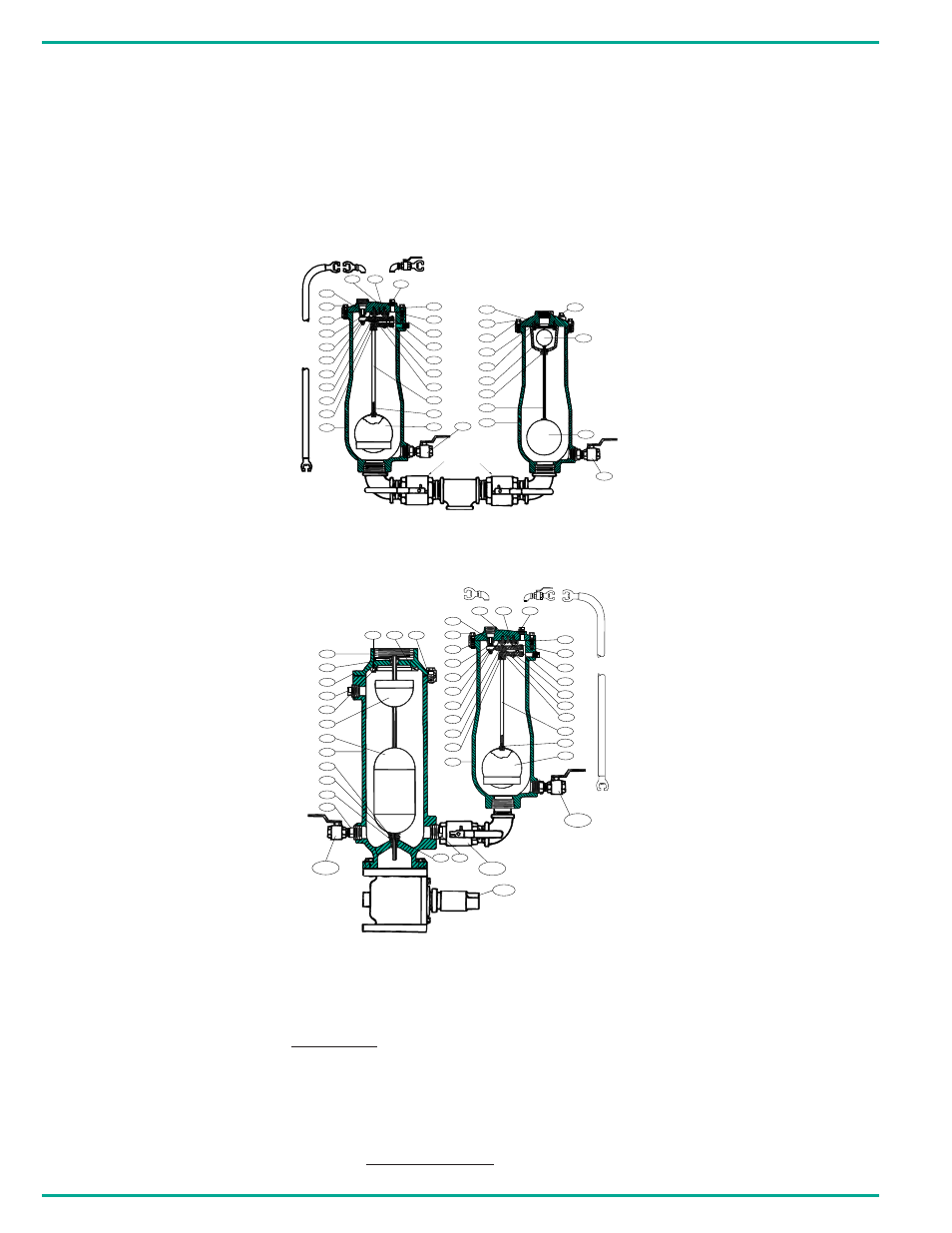
CUSTOM COMBINATION WASTE WATER AIR VALVES
INSTRUCTIONS AND PARTS LIST
SERIES MTP 36WW-BW
CANDELABRA STYLE
SERIES MTP 36WW-BW
SIDE MOUNTED STYLE
Detail No.
Part Name
Material
1
Body
Cast Iron ASTM A126, Class B
2
Cover
Cast Iron ASTM A126, Class B
3
Leverage Frame
Stainless Steel T304, ASTM A240
4
Seat
Stainless Steel T303, ASTM A276
5
Float
Stainless Steel T304, ASTM 240
6
Gasket
Lexide NK-511 (non-Asbestos)
7
Cover Bolt
Alloy Steel ASTM A449, Grade 5
8
Retaining Screws Stainless Steel T303, ASTM A276
10
Float Arm
Stainless Steel T303, ASTM A276
11
Orifice Button
Stainless Steel & Buna-N
®
12
Pivot Pin
Stainless Steel T303, ASTM A276a
13
Retaining Ring
Stainless Steel PH 15-7 Mo
14
Pipe Plug
Carbon Steel
17
Float Retainer
Stainless Steel, ASTM T18-8 A276
18
Lock Nut
Stainless Steel T304, ASTM A276
19
Link
Stainless Steel T304, ASTM A240
20
Guide Shaft
Stainless Steel T304, ASTM A269
21
Location Pin
Stainless Steel T420
22
Orifice Button
Stainless Steel T303, ASTM A276
30
Washer
Stainless Steel T18-8, ASTM A240
33
Clevis
Stainless Steel T304, ASTM A240
34
Lock Washer
Stainless Steel T304, ASTM A240
35
Retaining Screw
Stainless Steel T304, ASTM A240
Detail No.
Part Name
Material
1
Body
Cast Iron ASTM A126, Class B
2
Cover
Cast Iron ASTM A126, Class B
3
Leverage Frame
Stainless Steel T304, ASTM A240
4
Seat
Stainless Steel T303, ASTM A276
5
Float
Stainless Steel T304, ASTM 240
6
Gasket
Lexide NK-511 (non-Asbestos)
7
Cover Bolt
Alloy Steel ASTM A449, Grade 5
8
Retaining Screws
Stainless Steel T303, ASTM A276
10
Float Arm
Stainless Steel T303, ASTM A276
11
Orifice Button
Stainless Steel & Buna-N
®
12
Pivot Pin
Stainless Steel T303, ASTM A276a
13
Retaining Ring
Stainless Steel PH 15-7 Mo
14
Pipe Plug
Carbon Steel
17
Float Retainer
Stainless Steel, ASTM T18-8 A276
18
Lock Nut
Stainless Steel T304, ASTM A276
19
Link
Stainless Steel T304, ASTM A240
20
Guide Shaft
Stainless Steel T304, ASTM A269
21
Location Pin
Stainless Steel T420
22
Orifice Button
Stainless Steel T303, ASTM A276
30
Washer
Stainless Steel T18-8, ASTM A240
33
Clevis
Stainless Steel T304, ASTM A240
34
Lock Washer
Stainless Steel T304, ASTM A240
35
Retaining Screw
Stainless Steel T304, ASTM A240
Detail No.
Part Name
Material
1
Body
Cast Iron ASTM A126, Class B
2
Cover
Cast Iron ASTM A126, Class B
4
Seat
Buna-N
®
5
Float
Stainless Steel, T304 ASTM 240
6
Gasket
Lexide NK-511 (Non-Asbestos)
7
Cover Bolt
Alloy Steel
8
Retaining Screws
Stainless Steel ASTM A-276, T304
9
Guide Bushing
Stainless Steel ASTM A-276, T303
15
Cushion
Buna-N
®
26
Seat Retaining Sleeve
Stainless Steel ASTM A-276, T304
4.
Backflushing steps are basically the same for all sizes and styles of wastewater Air Release, Air and Vacuum and Combination
Valves but there are two ways to accomplish backflushing.
1. With clean water, that must be 15 PSI higher than the pressure in the force main, the valve may be flushed clean back into
the force main. Flush back into the force main by connecting hose C to valve D. Next open valve A and flush for 2-3 minutes
thru D. Next close D and switch hose C to E and flush for one minute. After flushing close valve A. Disconnect hose C and
vent pressure inside the Air Valve thru valve D. Next remove cover bolts (det 7.) remove top cover (det 2) for visual inspec -
tion and scrape out any grease. Use care to remove the cover and the cover gasket (det 3) may be re-used many times.
Reinstall cover (det. 2) and slowly open valve A.
2. With clean water that is not 15 psi higher pressure than the force main, backflush thru valve B into an atmospheric collection
tank. Follow the same procedure as above except close valve A and open valve B. After flushing remove cover to inspect
interior and replace cover same as above. Then close valve B, open valve A and the waste water valve is back in service.
Air Release Valve
Air and Vacuum Valve
Air Release Valve
BACKFLUSHING PROCEDURES
Detail No.
Part Name
Material
1
Body
Cast ASTM A126, Class B
2
Cover
Cast ASTM A126, Class B
3
Baffle
Ductile Iron ASTM A536
4
Seat
Buna-N
5
Float
Stainless Steel ASTM A-240, T304
5-L
Float
Stainless Steel ASTM A-240, T304
6
Gasket
Lexide Nk-511 (Non-Asbestos)
7
Cover Bolt
Alloy Steel ASTM ASTM A449 Grade 5
8
Retaining Screw Stainless Steel ASTM A-276, T304
9
Guide Bushing
Stainless Steel ASTM A-276, T3043
14
Cover Pipe Plug
Malleable Iron
20
Guide Shaft
Stainless Steel ASTM A-276, T304
Air and Vacuum Valve