E-60-31 4in and larger_2, Cla-val, Wiring diagram – Cla-Val 60-31/660-31 User Manual
Page 4
CLA-VAL
Copyright Cla-Val 2013 Printed in USA Specifications subject to change without notice.
P.O. Box 1325
• Newport Beach, CA 92659-0325 • Phone: 949-722-4800 • Fax: 949-548-5441 • E-mail: [email protected] • Website cla-val.com
©
Pilot System Specifications
When Ordering,
Please Specify
1. Catalog No. 60-31 or
No. 660-31
2. Valve Size
3. Pattern - Globe or Angle
4. Pressure Class (Flanged)
5. Trim Material
6. Electrical Selection
7. Desired Options
8. When Vertically Installed
(Flow Direction)
Note: For optimum operation of built-in check feature, installation with valve stem vertically position is recommended.
E-60-31/660-31 (R-1/2013)
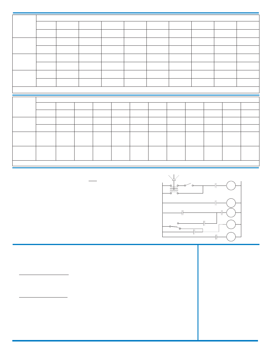
Auto
Off
Hand
L1
SW1
A
3CR3
L2
1CR
H
1CR
1CR
3CR1
N.C.
2CR
PVS
2CR
3CR
M
COM.
SW
2
N.O.
3CR
2
2CR
Auto-Off-Hand = Selector Switch
1CR = Relay, DPST Normally
Open
2CR = Relay, DPST Normally
Open
3CR = Relay, TPST Normally
Open
SW1 = Switch, Remote Start,
Automatic
SW2 = Switch, SPDT, Valve Limit
Switch Connect to N.C.
Terminal
PVS = Pilot Valve Solenoid
M =
Pump Motor Starter
Note:
SW2 and PVS supplied by
Cla-Val Co. All other electrical items
supplied by customer. SW2 is
included in the X105L switch
assembly which is mounted on the
pump control valve cover.
Shown In Pump Off Position
60-31
Valve
Selection
100-04 Pattern:
Globe (G), Angle (A),
End Connections:
Threaded (T), Flanged (F) Indicate Available Sizes
Inches
2
2
1
⁄
2
3
4
6
8
10
12
14
mm
50
65
80
100
150
200
250
300
350
Basic Valve
100-04
Pattern
G, A
G, A
G, A
G, A
G, A
G, A
G, A
G, A
G, A
End Detail
T, F
T, F
T, F
T, F
T, F
T, F
F
F
F
Suggested
Flow
(gpm)
Maximum
210
300
460
800
1800
3100
4900
7000
8400
Maximum
Intermittent
260
370
580
990
2250
3900
6150
8720
10540
Suggested
Flow
(Liters/Sec)
Maximum
13
19
29
50
113
195
309
442
530
Maximum
Intermittent
16
23
37
62
142
246
387
549
664
100-04 Series is the full internal port Hycheck.
660-31
Valve
Selection
100-23 Pattern:
Globe (G), Angle (A),
End Connections:
Flanged (F) Indicate Available Sizes
Inches
3
4
6
8
10
12
14
16
18
20
24
mm
80
100
150
200
250
300
350
400
450
500
600
Basic Valve
100-23
Pattern
G
G, A
G, A
G, A
G
G
G
G
G
G
G
End Detail
F
F
F
F
F
F
F
F
F
F
F
Suggested
Flow
(gpm)
Maximum
260
580
1025
2300
4100
6400
9230
9230
16500
16500
16500
Suggested
Flow
(Liters/Sec)
Maximum
16
37
65
145
258
403
581
581
1040
1040
1040
100-23 Series is the reduced internal port size version of the 100-04 Series.
Temperature Range
Water: to 180°F Max
Materials
Standard Pilot System Materials
Pilot Control:
Bronze ASTM B62
Trim:
Stainless Steel Type 303
Rubber:
Buna-N
®
Synthetic Rubber
Optional Pilot System Materials
Pilot Systems are available with optional
Stainless Steel or Monel materials
Solenoid Contro
l
Body:
Brass ASTM B283
Enclosure:
General Purpose, Watertight 1,2,3,3S,4,4X
Optional: Class I, Division 2, Hazardous Locations
and Watertight Type 3, 3S, 4, 4X
Voltages:
100-240 V 50-60 Hz AC or DC
24-99 V 50-60 Hz AC or DC
2-24 V DC
Manual Operator Standard
Max. operating pressure differential: 300 psi
Coil:
Insulation molded Class
F
Watts AC
2
Wiring Diagram