E-60-31 4in and larger_5, Materials pressure ratings, 31 series dimensions – Cla-Val 60-31/660-31 User Manual
Page 3
Materials
Pressure Ratings
(Recommended Maximum Pressure - psi)
Valve Body & Cover
Pressure Class
Flanged
Grade
Material
ANSI
Standards*
150
Class
300
Class
ASTM A536
Ductile Iron
B16.42
250
400
ASTM A216-WCB
Cast Steel
B16.5
285
400
ASTM B62
Bronze
B16.24
225
400
Note:
* ANSI standards are for flange dimensions only.
Flanged valves are available faced but not drilled.
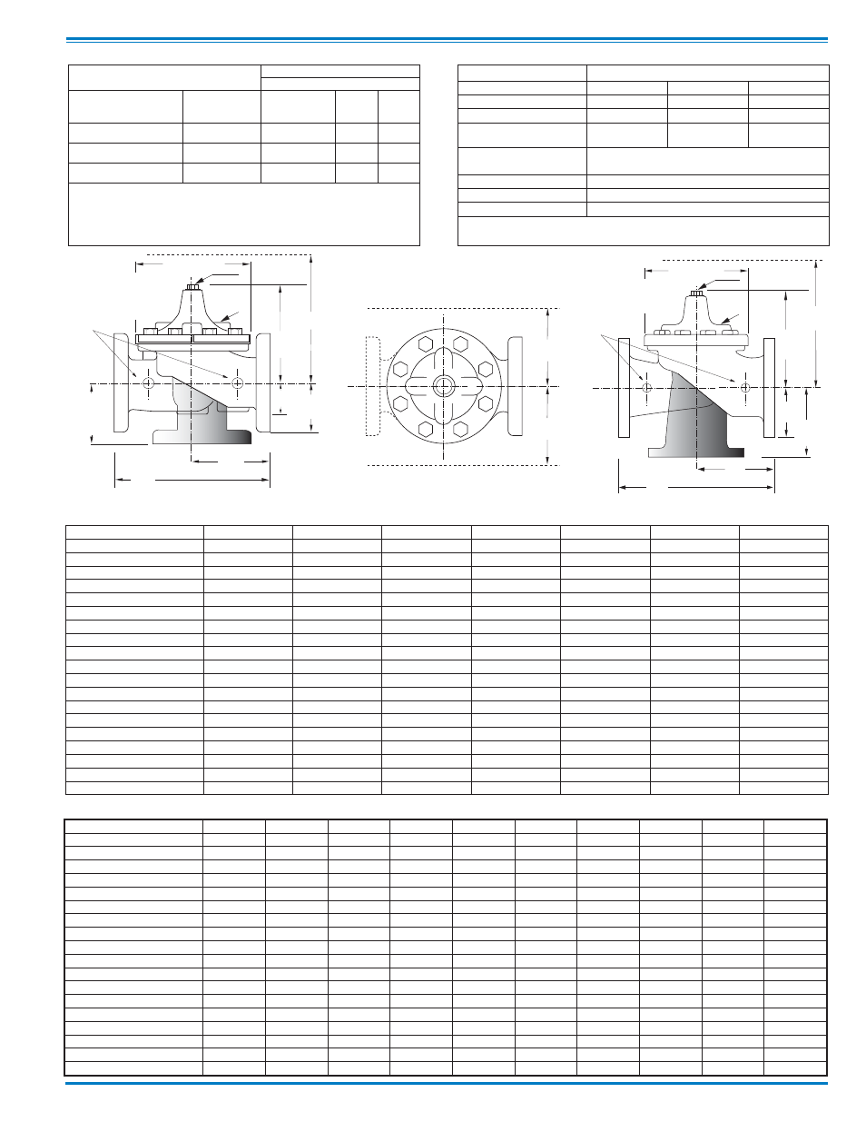
660-31 Series Dimensions
(Reduced Internal Port 100-23)
(In Inches)
Component
Standard Material Combinations
Body & Cover
Ductile Iron
Cast Steel
Bronze
100-04 Available Sizes
4" - 16"
4" - 16"
4" - 16"
100-23 Available Sizes
4" - 24"
4" - 16"
4" - 16"
Disc Retainer &
Diaphragm Washer
Cast Iron
Cast Steel
Bronze
Trim: Disc Guide,
Seat & Cover Bearing
Bronze is Standard
Stainless Steel is Optional
Disc
Buna-N
®
Rubber
Diaphragm
Nylon Reinforced Buna-N
®
Rubber
Stem, Nut & Spring
Stainless Steel
For material options not listed, consult factory.
Cla-Val manufactures valves in more than 50 different alloys.
GG
GGG
Inlet
DD
DDD
F
FF
X
100-04
Flanged
E
C
(MAX)
K
J
H
Inlet
Outlet
AA
AAA
B
(Diameter)
EE
D
E
Inlet
DD
AA
X
100-23
Flanged
F
A
C
(MAX)
K
J
H
Inlet
Outlet
FF
B
(Diameter)
Y
Z
60-31 Series Dimensions
(Full Internal Port 100-04)
(In Inches)
Valve Size
(Inches)
4
6
8
10
12
14
16
AA 150 ANSI
15.00
20.00
25.38
29.75
34.00
39.00
41.38
AAA 300 ANSI
15.62
21.00
26.38
31.12
35.50
40.50
43.50
B Dia.
11.50
15.75
20.00
23.62
28.00
32.75
35.50
C Max.
10.62
13.38
16.00
17.12
20.88
24.19
25.00
DD 150 ANSI
7.50
10.00
12.69
14.88
17.00
19.50
20.69
DDD 300 ANSI
7.81
10.50
13.19
15.56
17.75
20.25
21.75
E
3.19
4.31
5.31
9.25
10.75
12.62
15.50
F 150 ANSI
4.50
5.50
6.75
8.00
9.50
10.50
11.75
FF 300 ANSI
5.00
6.25
7.50
8.75
10.25
11.50
12.75
GG 150 ANSI
5.00
6.00
8.00
8.62
13.75
14.88
15.69
GGG 300 ANSI
5.31
6.50
8.50
9.31
14.50
15.62
16.50
H NPT Body Tapping
3
⁄
4
3
⁄
4
1
1
1
1
1
J NPT Cover Center Plug
3
⁄
4
3
⁄
4
1
1
1
1
⁄
4
1
1
⁄
2
2
K NPT Cover Tapping
3
⁄
4
3
⁄
4
1
1
1
1
1
Stem Travel
1.1
1.7
2.3
2.8
3.4
4.0
4.5
Approx. Ship Wt. Lbs.
140
285
500
780
1165
1500
2265
X Pilot System
17
29
31
33
36
40
40
Y Pilot System
12
20
22
24
26
29
30
Z Pilot System
12
20
22
24
26
29
30
Valve Size
(Inches)
4
6
8
10
12
14
16
18
20
24
A 150 ANSI
13.88
17.75
21.38
26.00
30.00
34.25
35.00
42.12
48.00
48.00
AA 300 ANSI
14.50
18.62
22.38
27.38
31.50
35.75
36.62
43.63
49.62
49.75
B Dia.
9.12
11.50
15.75
20.00
23.62
27.47
28.00
35.44
35.44
35.44
C Max.
8.62
11.62
15.00
17.88
21.00
20.88
25.75
25.00
31.50
31.50
D 150 ANSI
6.94
8.88
10.69
—
—
—
—
—
—
—
DD 300 ANSI
7.25
9.38
11.19
—
—
—
—
—
—
—
E 150 ANSI
5.50
6.75
7.25
—
—
—
—
—
—
—
EE 300 ANSI
5.81
7.25
7.75
—
—
—
—
—
—
—
F 150 ANSI
4.50
5.50
6.75
8.00
9.50
11.00
11.75
15.88
14.56
17.00
FF 300 ANSI
5.00
6.25
7.50
8.75
10.25
—
12.75
15.88
16.06
19.00
H NPT Body Tapping
.50
.75
.75
1
1
1
1
1
1
1
J NPT Cover Center Plug
.50
.75
.75
1
1
1.25
1.25
2
2
2
K NPT Cover Tapping
.50
.75
.75
1
1
1
1
1
1
1
Stem Travel
0.8
1.1
1.7
2.3
2.8
3.4
3.4
4.5
4.5
4.5
Approx. Ship Wt. Lbs.
85
195
330
625
900
1250
1380
1500
2551
2733
X Pilot System
15
27
30
33
36
36
41
40
46
55
Y Pilot System
11
18
20
22
24
26
26
30
30
30
Z Pilot System
11
18
20
22
24
26
26
30
30
30