E-61-02_2, Cla-val, When ordering, please specify – Cla-Val 61-02KO/661-02KO Valve User Manual
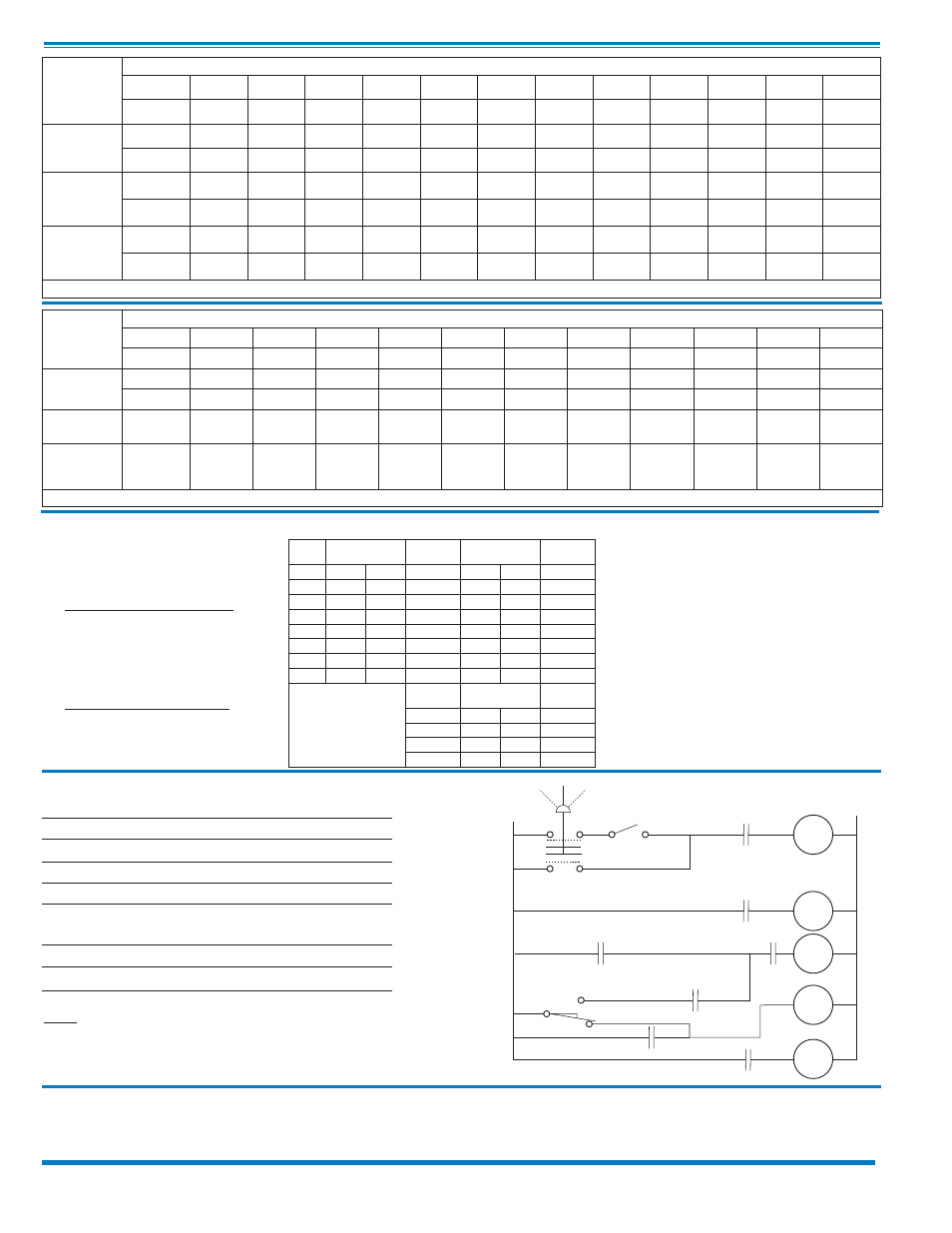
Page 4: Wiring diagram
CLA-VAL
Copyright Cla-Val 2013 Printed in USA Specifications subject to change without notice.
P.O. Box 1325
• Newport Beach, CA 92659-0325 • Phone: 949-722-4800 • Fax: 949-548-5441 • E-mail: [email protected] • Website cla-val.com
©
E-61-02/661-02 (R-1/2013)
Temperature Range
Water to 180°F Max
Materials
Standard Pilot System Materials
Pilot Control: Bronze ASTM B62
Trim: Stainless Steel
Type 303
Rubber: Buna-N
®
Synthetic
Rubber
Optional Pilot System Materials
Pilot Systems are available with
optional Aluminum, Stainless Steel
or Monel materials.
Pilot System Specifications
CSM11 Solenoid Control Power Consumption & Specifications
Enclosure General purpose NEMA Type 3; Aluminum
Note: For other enclosures and
NEMA Types, consult factory
Housing
Body — Aluminum
Trim — Stainless Steel
Operating Pressure: Maximum pressure 300 psi,
for higher pressure consult factory. AC or DC
Coil Insulation
Class A (molded)
AC voltage
15.4 watts
DC voltage
16.8 watts
Auto
Off
Hand
L1
SW1
A
3CR3
L2
1CR
H
1CR
1CR
3CR1
N.C.
2CR
PVS
2CR
3CR
M
COM.
SW
2
N.O.
3CR
2
2CR
Auto-Off-Hand
=
Selector Switch
1CR
=
Relay, DPST Normally Open
2CR
=
Relay, DPST Normally Open
3CR
=
Relay, TPST Normally Open
SW1
=
Switch, Remote Start, Automatic
SW2
=
Switch, SPDT, Valve Limit Switch
Connect to N.C. Terminal
PVS
=
Pilot Valve Solenoid
M
= Pump Motor Starter
Note: SW
2
and PVS supplied by Cla-Val. All other electrical items
supplied by customer. SW
2
is included in the X105L switch
assembly which is mounted on the pump control valve cover.
Shown In Pump Off Position
Volts
Amperes
Volts
Amperes
Coil
Resistance
DC
Holding Pull In AC 60 Hz Holding Inrush
Ohms
24
.603
24
24
2.88
25.4
0.5
28
.629
120
120
.575
5.1
14.1
32
.500
208
208
.330
2.93
40
48
.293
240
240
.288
2.54
58
115
.122
440
440
.156
1.38
174
125
.119
480
440
.143
1.27
233
252
.072
2.45
Volts
Amperes
Coil
Resistance
(AC 50 Hz) Holding Inrush
Ohms
110
.48
4.6
15.7
220
.24
2.3
66
240
.22
2.1
88
When Ordering, Please Specify:
1. Catalog No. 61-02/661-02 2. Valve Size 3.
Pattern -Globe or Angle 4. Pressure Class 5. Trim Material
6. Electrical Selection 7. Desired Options 8.
When Vertically Installed (Flow Direction)
Note: For main valve option descriptions, refer to 100-02 (61-02) or 100-21 (661-02 Technical Data Sheets.
61-02
Valve
Selection
100-02 Pattern:
Globe (G), Angle (A),
End Connections:
Threaded (T), Flanged (F) Indicate Available Sizes
Inches
2
1
⁄
2
3
4
6
8
10
12
14
16
18
20
24
mm
65
80
100
150
200
250
300
350
400
450
500
600
Basic Valve
100-02
Pattern
G, A
G, A
G, A
G, A
G, A
G, A
G, A
G, A
G, A
G
G
G, A
End Detail
T, F
T, F
F
F
F
F
F
F
F
F
F
F
Suggested
Flow
(gpm)
Maximum
300
460
800
1800
3100
4900
7000
8400
11000
14000
17000
25000
Maximum
Intermittent
370
580
990
2250
3900
6150
8720
10540
13700
17500
21700
31300
Suggested
Flow
(Liters/Sec)
Maximum
19
29
50
113
195
309
442
530
694
883
1073
1577
Maximum
Intermittent
23
37
62
142
246
387
549
664
863
1104
1369
1972
100-02 Series is the full internal port Powertrol.
661-02
Valve
Selection
100-21 Pattern:
Globe (G), Angle (A),
End Connections:
Flanged (F) Indicate Available Sizes
Inches
3
4
6
8
10
12
14
16
18
20
24
mm
80
100
150
200
250
300
350
400
450
500
600
Basic Valve
100-21
Pattern
G
G, A
G, A
G, A
G
G
G
G
G
G
G
End Detail
F
F
F
F
F
F
F
F
F
F
F
Suggested
Flow (gpm)
Maximum
260
580
1025
2300
4100
6400
9230
9230
16500
16500
16500
Suggested
Flow
(Liters/Sec)
Maximum
16
37
65
145
258
403
581
581
1040
1040
1040
100-21 Series is the reduced internal port size version of the 100-02 Series.
Wiring Diagram