E-61-02_4, Sequence of operation, Valve selection chart cv values – Cla-Val 61-02KO/661-02KO Valve User Manual
Page 2: Selecting the valve
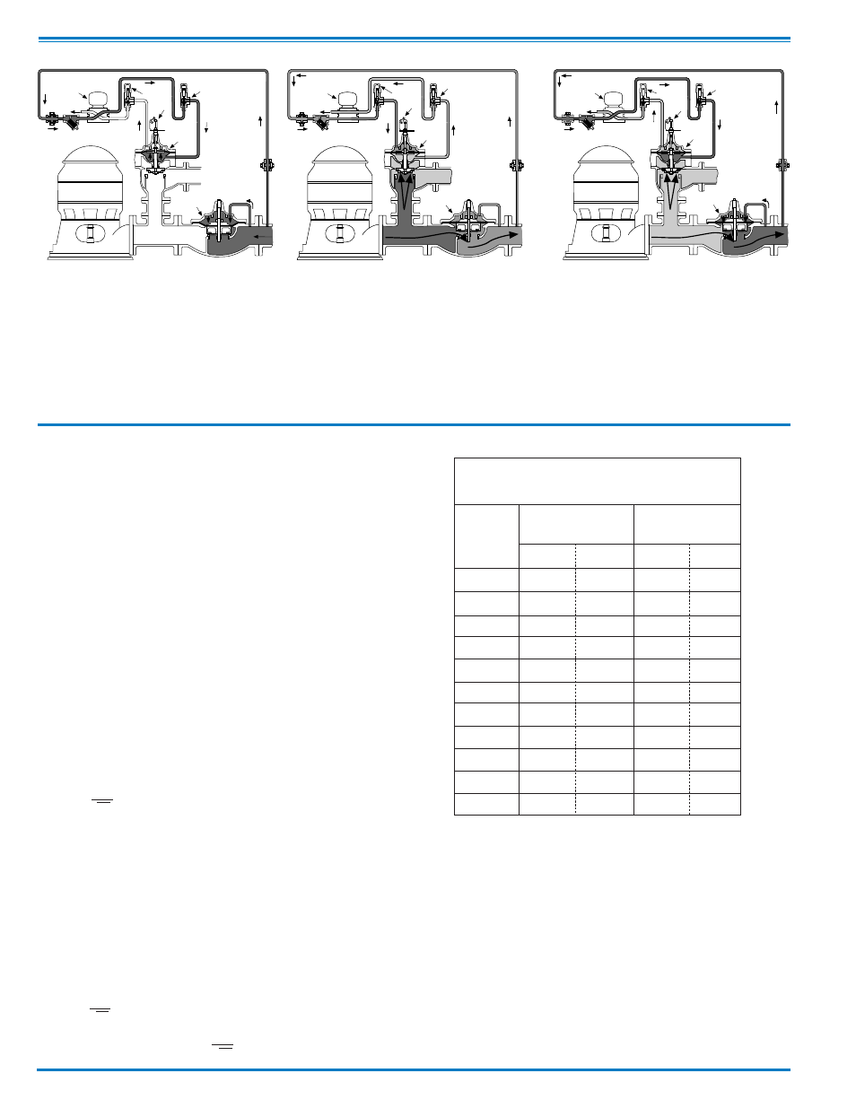
Pump Off...
With pump off, static line pressure holds the
main line check valve “B” closed. Line pres-
sure is transmitted through solenoid control
“C” and speed control “D” to the lower cham-
ber of valve “A”. Upper chamber of pump
control valve “A” is vented to atmosphere so
valve “A” is held wide open.
Starting Cycle...
Starting switch closes, pump starts, solenoid
“C” energizes and shifts, allowing line pressure
to flow into upper chamber of valve “A” through
solenoid control “C” and opening speed control
“E”. Closing speed of valve “A“ is controlled by
speed control “D“ which limits the rate fluid is
relieved from under the diaphragm. As valve
“A” closes, pumping pressure opens main line
check valve “B”, gradually permitting full flow.
Sequence Of Operation
Drain
c
Supply
P.T.1
P.T.2
E
F
D
A
B
Drain
Supply
c
E
F
D
A
B
P.T.1
P.T.2
C
Drain
Supply
P.T.1
P.T.2
E
F
D
A
B
Stopping Cycle...
Starting switch opens, solenoid “C” de-energizes
and shifts, as pump continues to run, pump pres-
sure flows into lower chamber of valve “A” through
solenoid “C” and opening speed control “D”.
Pressure in upper chamber of valve “A” is relieved
to atmosphere through opening speed control “E”
and solenoid control “C”.As valve “A” opens, flow
through main line check valve “B” gradually
lessens until valve “A” is wide open and the limit
switch “F” shuts off the pump.
Valve Selection Chart
Cv Values
Valve
Globe
Angle
Size
61-02
661-02
61-02
661-02
2
1
⁄
2
85
–
101
–
3
115
62
139
–
4
200
136
240
135
6
460
229
541
233
8
770
480
990
545
10
1245
930
1575
–
12
1725
1458
2500
–
14
2300
–
3060
–
16
2940
2110
4200
–
20
–
3400
–
–
24
–
3500
–
–
To be effective, this valve must be sized so it relieves to atmosphere
that part of the pump discharge head which is in excess of the nor-
mal system static pressure. To do this, the valve is sized to permit
the full pump discharge through the valve at a pressure low enough
to keep the system check valve from opening. As the pump control
valve closes, the pumping pressure exceeds the system pressure
and gradually flows into the system.
We recommend selecting a valve size which will have a pressure
loss that is at least 10 psi less than the system static pressure. Use
the flow rate which is found on the pump's flow vs discharge pres-
sure chart. Select the flow corresponding to the system static pres-
sure, less 10 psi.
Determining Valve Size
1. Determine the system's static pressure (the pressure
downstream of the check valve with the pump off); subtract
10 psi, this is the Design Pressure P.
2. From the pump's flow vs. discharge pressure curve,
determine the flow (Q) at the Design Pressure P.
3. Using the formula, calculate the Cv.
Cv =
Q
√ P
4. Select the valve size from the table which has a Cv that is
equal to, or greater than, the calculated Cv in step 3 above.
Example:
1. System Static Pressure with the pump off = 70 psi.
2. Determine the Design Pressure P by subtracting 10 psi
(70 psi - 10 psi = 60 psi Design Pressure)
3. From the pump curve we determine that the valve must
allow a flow of 800 GPM at 60 psi.
4. Using the Formula:
Cv =
Q
Where:
Q = 800 GPM
√
P
P = 60 psi (70 psi - 10 psi)
5. From the table above the best valve choices are:
3"
6 1 - 0 2
Globe Pattern
4"
661-02
Globe Pattern
4"
661-02
Angle Pattern
Drain Provisions
Each time the valve opens or closes, water is dis-
charged from the solenoid exhaust port, the amount
varying with the valve size. Provisions should
be made for the disposal of this water. Exhaust
tube must be free of any back pressure. Provide
an air gap between the solenoid exhaust tube and drain
facility.
Selecting The Valve
Cv =
800
=103
√
60
Example