Ii. low pressure override feature, Iii. x78-4 adjustable orifice assembly feature, Iv. accumulator feature – Cla-Val 98-06/698-06 Quick Manual User Manual
Page 3: V. 6120 needle valve feature, Vi. optional feature operating data, X78-4 adjustment table
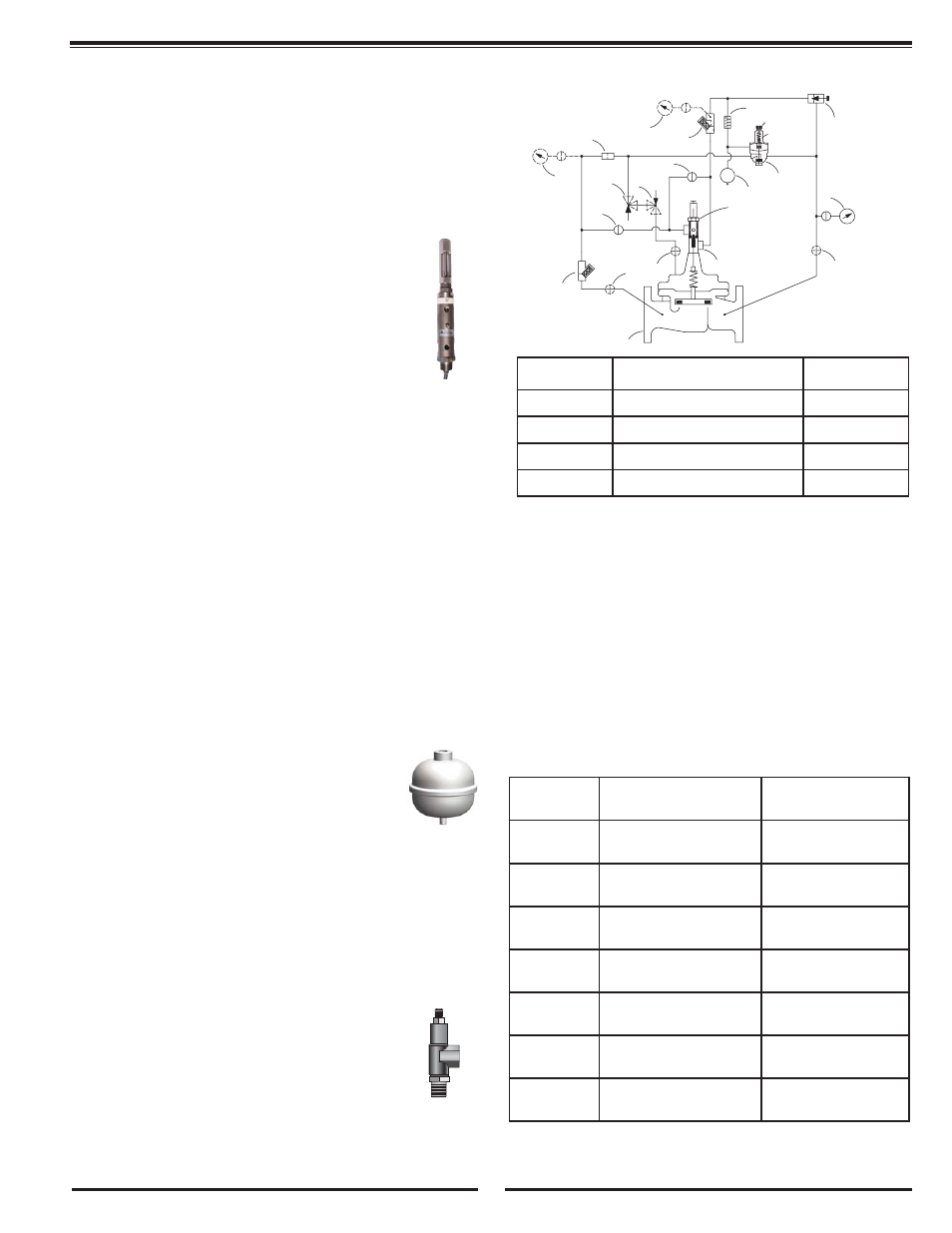
II. LOW PRESSURE OVERRIDE FEATURE
To override an established low pressure set point of the CPM-A (4),
open Isolation Valve (6B). Low pressure set point is disabled and Main
Valve (1) regulates at the high pressure set point as long as the
Isolation Valve (6B) remains open. To restore the low pressure set
point condition, close Isolation Valve (6B).
III. X78-4 ADJUSTABLE ORIFICE ASSEMBLY FEATURE
The Adjustable Orifice Assembly is comprised of the
X78-4 Adjustable Orifice + the X101 Valve Position
Indicator.
The X78-4 Adjustable Orifice Assembly (5) is used to
increase the transition point (% open) between low and
high pressure set points of the CPM-A (4).
Prior to adjusting the X78-4 (5) feature, loosen the set
screw on the side of the X78-4 housing approximately
1/2 turn. The set screw is located near the top of the
X78-4 housing. To lower downstream pressure at the
current (or known) flow rate, turn the X78-4 adjustment screw clockwise
until the pressure reading at the gauge (8) drops to the low pressure set
point of the CPM-A (4). The X78-4 adjustment screw can be turned by
hand or with an open end wrench.
Note:
Adjusting the X78-4 shifts the flow point where the pressure conditions
starts to transition between low and high pressure set points. By turn-
ing the adjustment screw counter-clockwise on the X78-4, the transition
between the low and high pressure set points occurs at a lower flow
rate. As an example: When the X78-4 adjustment screw is turned
counter-clockwise until bottomed, the transition between low and high
pressure set points starts at the lowest possible flow rate. Turning the
X78-4 adjustment screw clockwise changes the transition point to a
higher flow rate. The X78-4 Adjustment Table can be used as a guide-
line to determine valve position change (% open) per turn of the X78-4
adjustment screw.
IV. ACCUMULATOR FEATURE
The Accumulator (11) functions as a pressure transition
dampening device that allows for a relatively smooth
transition between low and high pressure set points of
the Model 98-06/698-06 Pressure Management Valve.
The Accumulator is factory air charged to approximate-
ly 51 psi (3.5 bar). This pre-charge condition is satisfac-
tory for most Model 98-06/698-06 applications and no
additional field charging is required.
If the low pressure set point condition is greater than 80 psi (5.5 bar),
then a slightly higher accumulator air charge pressure may be desir-
able. The accumulator is equipped with a stem valve, similar to a stem
valve used on bicycle or vehicle tires. Air charge pressure can be
changed using a hand tire pump or an air pressure source from a gas
station.
V. 6120 NEEDLE VALVE FEATURE
The 6120 Needle Valve (9) is used to regulate or bal-
ance pressure into and out of the sensing chamber of
the CPM-A Pressure Management Control.
For normal operation, the 6120 Needle Valve is adjust-
ed approximately two turns out. When he 6120 Needle
Valve is turned all the way in, the Main Valve will only
regulate at the high pressure set point of the CPM-A.
When the 6120 Needle Valve is adjusted more than five turns out,
the Main Valve will only regulate at the low pressure set point of
the CPM-A.
VI. OPTIONAL FEATURE OPERATING DATA
Suffix B- Isolation Valve
CK2 Isolation Valves (B) are used to isolate the pilot system from
the main line pressure. These valves must be open during normal
operation.
Suffix C - Closing Speed Control
The CV Flow Control (C) controls the closing speed of the Main
valve. Turn the adjusting stem clockwise to make the Main Valve
close slower.
Suffix S - Opening Speed Control
The CV Flow Control (S) controls the opening speed of the Main
Valve. Turn the adjusting stem clockwise to make the Main Valve
open slower.
X78-4 Adjustment Table
% Position change is the % change in Main Valve opening
per turn of the X78-4 Adjustment Screw.
2
INLET
B
B
6A
P1
S
C
6B
3
7
1
5
9
ADJUSTMENT
HIGH PRESSURE
10
LOW
ADJUSTMENT
PRESSURE
11
4
B
8
ADJUSTMENT SCREW
P2
Model #
Suffix
Item
Quantity
B
CK2 Isolation Valve
3
C
CV Flow Control (Closing)
1
P
X141 Gauge Assembly
2
S
CV Flow Control (Opening)
1
Valve Size
X78-4 (5)
Total Travel
% Position Change
Per Turn
2” 100-01
3” 100-20
.40” (10 mm)
9.9%
2-1/2” 100-01
.40” (10 mm)
8.2%
3” 100-01
4” 100-20
.40” (10 mm)
7.0%
4” 100-01
6” 100-20
.80” (20 mm)
5.3%
6” 100-01
8”100-20
.80” (20 mm)
3.7%
8”100-01
10” 101-20
1.40” (35 mm)
2.6%
10” 100-01
12” 100-20
1.40” (35 mm)
1.8%
3