Checklist for proper operation, I. pressure management control feature, Cpm-a standard adjustment procedure – Cla-Val 98-06/698-06 Quick Manual User Manual
Page 2
CHECKLIST FOR PROPER OPERATION
Perform the following steps prior to start-up:
I. PRESSURE MANAGEMENT CONTROL FEATURE
The CPM-A Pressure Management Control (4) is a normally open control
that responds to change in downstream demand. Downstream pressure
is managed between high and low flow system conditions. When system
demand is normal or higher than normal, the CPM-A Pressure
Management Control maintains downstream pressure at the high pres-
sure set point. An increase in outlet pressure closes the control and a
decrease is outlet pressure closes the control. This causes the Main
Valve Cover pressure to vary and the Main Valve modulates (opens and
closes), maintaining the downstream pressure at the high set point.
When system demand decreases below normal demand, the CPM-A
Control responds by gradually lowering the downstream pressure until it
reaches the low pressure set point. As system flow changes between the
low and high pressure set points, the CPM-A Control closes or opens
accordingly. This causes the Main Valve Cover pressure to vary and the
Main Valve modulates (opens and closes), maintaining the downstream
pressure at either the low or high pressure set point.
CPM-A STANDARD ADJUSTMENT PROCEDURE:
Two methods of adjustment are possible for the CPM-A Pressure
Management Control. Method I is the most accurate adjustment method
and requires the ability to have a means to adjust system flow rates dur-
ing the adjustment process. A gate valve downstream of the Main Valve
is an acceptable device for approximating the low flow condition.
Method II is intended for use if an approximation of the pressure span
adjustment (low pressure set point) is acceptable and there is not a prac-
tical means to vary system flow during the adjustment procedure.
METHOD I
System flow should be equal to or slightly greater than the normal expect-
ed system flow at the start of the adjustment procedure.
1) Isolation Valve (6B) is closed. Isolation Valve (6A) is open
2) Adjust 6120 Needle Valve 2 turns out from the fully closed position
3) Turn the X78-4 (5) adjustment screw counter-clockwise until
stopped.
4) Turn the CPM-A (4) low pressure adjustment screw clockwise until
stopped (LP = HP). Low pressure adjustment screw is inside the
cover chamber. There is an access hole through the HP adjust-
ment screw and thee screw has a screwdriver slot
5) Turn the CPM-A (4) high pressure adjustment screw until the
pressure at the gauge (8) is at the desired maximum system
downstream pressure condition
6) Close Isolation Valve (6A)
7) Slowly turn the CPM-A (4) low pressure adjustment screw out,
counter-clockwise, until pressure at gauge (8) starts to dip.
Continue to adjust until pressure at gauge (8) is at the desired
low pressure set point
8) Open Isolation Valve (6A)
METHOD I (continued)
9) To adjust the X78-4 (5) when system flow is at or near normal
demand status, turn the X178-4 adjustment screw clockwise until
pressure at gauge (8) dips to low pressure set point condition.
Next turn the X78-4 (5) adjustment screw counter-clockwise one
turn. At this adjustment position, the system pressure remains at
the high pressure set point until valve position decreases to the
adjusted point position of the X78-4 (5). Refer to the X78-4
Adjustment Table for position per turn. Per the X78-4 (5)
Adjustment Table on page 3, at 1 clockwise turn, a 4-inch valve
will transition to the low pressure set point when valve position
decreases approximately 5.3%. Further adjustment may be nec-
essary to achieve the desired transition point between high and
low pressure set points.
METHOD II
System flow should be approximately equal to the expected low flow
condition for the system at the start of the adjustment procedure.
1) Isolation Valves (6A and 6B) are open
2) Adjust 6120 Needle Valve so it is two turns out from fully closed
3) Turn the X78-4 (5) adjustment screw counter-clockwise until
stopped.
4) Turn the CPM-A (4) low pressure adjustment screw clockwise until
stopped
5) Turn the CPM-A (4) high pressure adjustment screw until the
pressure at the gauge (8) is at the desired maximum system
downstream pressure condition
6) Close Isolation Valves (6A and 6B)
7) Slowly turn the CPM-A (4) low pressure adjustment screw out,
counter-clockwise, until pressure at gauge (8) starts to dip.
Continue to adjust until pressure at gauge (8) is at the desired low
pressure set point
8) Open Isolation Valve (6A)
9) To adjust the X78-4 (5) when system flow is at or near normal
demand status, turn the X178-4 adjustment screw clockwise two
turns. At this adjustment position, the system pressure remains at
the low pressure set point until valve position increases to a
position change according to the X78-4 Adjustment Table - pg.3.
When valve position increases to the adjustment setting of the
X78-4 (5), system pressure increases to the CPM-A (4) high
pressure set point, indicating system demand has increased.
Per the X78-4 Adjustment Table, at two clockwise turns, a 4-inch
valve will transition to the high pressure set point when a valve
position increases approximately 10.6% (2 X 5.3%). Further
adjustment may be necessary to achieve desired transition point
between high and low pressure set points.
Note: Adjustment Methods I & II are intended only to approximate the
low and high pressure set point conditions if there is no means to
independently control system flow or establish a desired pressure
transition flow condition. The X78-4 Adjustable Orifice Assembly (5)
may require slight re-adjustment during actual low flow conditions in
order to establish the desired pressure transition condition. Cla-Val
recommends recording pressure and flow data as a means of eval-
uating daily or periodic pressure and flow trends in the system. This
data can be utilized to make additional adjustments to the Pressure
Management Control Valve and optimize the pressure management
conditions within the system. Consult factory for Cla-Val data logging
products (such as the X142FPT Flow and Pressure Tracker and the
X144 e-FlowMeter) which can be used with this valve to achieve opti-
mum performance.
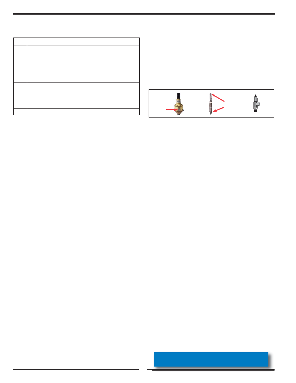
CPM-A
X78-4
6120
√
Open upstream and downstream System Valves.
√
- Remove air from Main Valve Cover and Pilot System at all
high points:
- The Variable Orifice Assembly (5) has an air bleed screw
located on the top of the X101 Valve Position Indicator and one
on the bottom of the X78-4 (see photos at right).
- The CPM-A (4) has an air bleed screw in the fitting located
on the sensing chamber of the control.
√
Pilot System Isolation Valve (6A) should be open and Pilot System
Isolation Valve (6B) should be close during normal operation.
√
Open optional CK2 Isolation Valve (Suffix B) during normal operation.
√
CV Speed Controls (C and S) should be full open (adjusting stem
backed all the way out) at initial start-up. After start-up, monitor sys-
tem conditions when making adjustments to optional CV Speed
Controls (C and S)
√
Periodically clean X43 and X44A Strainers (2 and 7)
call 800.942.6326 for assistance or log-on to
www.cla-val.com for more information
2
air bleed
screw
air bleed
screw