Installation and maintenance instructions, Bulletin 8320 – Cla-Val 136-01/636-01 Technical Manual User Manual
Page 19
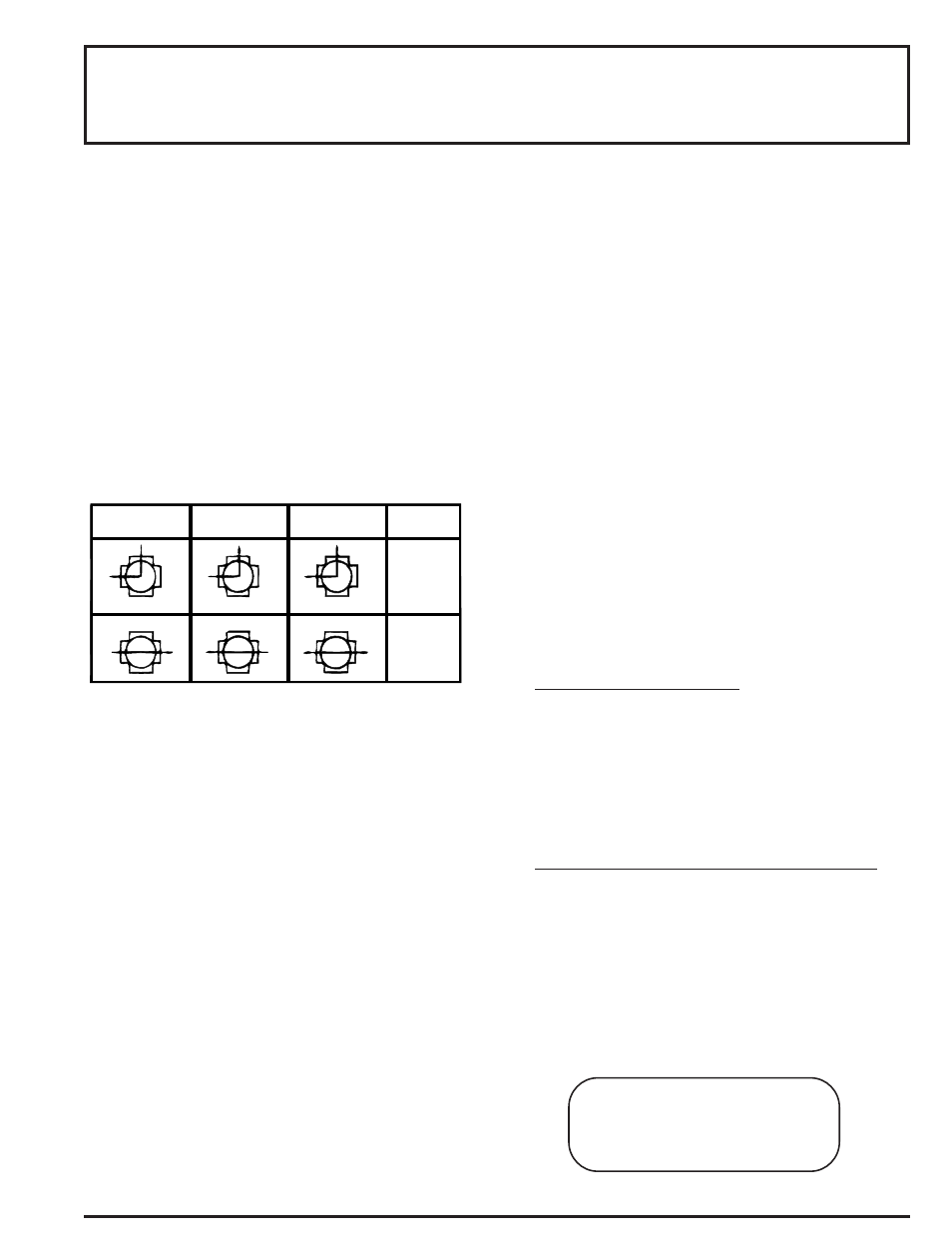
NORMALLY OPEN
PRESS AT 3 (C)
NORMALLY CLOSED
PRESS AT 3 (C)
UNIVERSAL-PRESS
AT ANY ORIFICE.
FORM
SOLENOID
DE-
ENERGIZED
SOLENOID
ENERGIZED
3
I
(C)
2
(B)
(A)
3
I
(C)
2
(B)
(A)
3
I
(C)
2
(B)
(A)
3
I
(C)
2
(B)
(A)
3
I
(C)
2
(B)
(A)
3
I
(C)
2
(B)
(A)
DESCRIPTION
MANUAL OPERATORS (OPTIONAL)
NOTE: Port Markings 1, 2, and 3 correspond directly to A,
B and C.
Bulletin 8320 is a small 3-way solenoid operated valve with all three
pipe connections located in the body. The bodies are of brass or stain-
less steel construction. Standard valves have General Purpose, Nema
Type 1 Solenoid Enclosures. Valves that are equipped with a solenoid
enclosure which is designed to meet Nema Type 4-Water tight, Nema
Type 7 (C or D) Hazardous Locations - Class I, Group C or D, and
Nema Type 9 (E, F or G) Hazardous Locations - Class II, Group E, F or
G are shown on separate sheets of Installation and Maintenance
Instructions, Form Numbers V-5391 and V-5381.
Check Nameplate for correct Catalog Number, pressure, voltage and
service.
Valves with suffix "MO" or "MS" in catalog number are provided with a
Manual Operator which allows manual operation when desired or dur-
ing an interruption of electrical power.
INSTALLATION
Valve may be mounted in any position
POSITIONING
Connect piping to valve according to markings on valve body. Refer to
Flow Diagram provided. Apply pipe compound sparingly to male pipe
threads only; if applied to valve threads, it may enter valve and cause
operational difficulty. Pipe strain should be avoided by proper support
and alignment of piping. When tightening pipe, do not use valve as
lever.
PIPING
Wiring must comply with local and National Electrical Codes. For
valves equipped with an explosion-proof, watertight solenoid enclo-
sure, the electrical fittings must be approved for use in the approved
hazardous locations. Housings for all solenoids are made with connec-
tions for 1/2 inch conduit. The general purpose enclosure may be rotat-
ed to facilitate wiring by removing the retaining cap.
WIRING
OPERATION
Normally Closed: Applies pressure when solenoid is energized:
exhausts pressure when solenoid is de-energized
Normally Open: Applies pressure when solenoid is de-energized;
exhausts pressure when solenoid is energized.
Universal: For normally closed or normally open operation, selection
or diversion of pressure can be applied at port 1 (A), 2 (B), or 3 (C).
NOTE
SOLENOID TEMPERATURE
MAINTENANCE
COIL REPLACEMENT
(REF. FIG. 2)
Alternating Current (A-C) and Direct Current (D-C) solenoids are built
differently. To convert from one to other, it is necessary to change the
complete solenoid, including the core assembly.
Turn off electrical power, disconnect coil lead wires and proceed as
follows:
Spare Parts Kits and Coils are available for ASCO valves. Parts
marked with
Standard catalog valves are supplied with coils designed for contin-
uous duty service. When the solenoid is energized for a long period,
the solenoid enclosure becomes hot and can be touched with the
bare hand for only an instant. This safe operating temperature. Any
excessive heating will be indicated by the smoke and odor of burn-
ing coil insulation.
CLEANING
A periodic cleaning of all valves is desirable. The time between
cleanings will vary, depending on the media and service conditions.
In general, if the voltage to the coils is correct, sluggish valve oper-
ation or excessive leakage will indicate that cleaning is required.
IMPROPER OPERATION
Faulty Control Circuit: Check the electrical system by energiz-
ing the solenoid. A metallic click signifies the solenoid is operat-
ing. Absence of the click indicate loss of power supply. Check for
loose or blown-out fuses, open-circuited or grounded coil, broken
lead wires or splice.
Burned-out Coil: Check for open-circuited coil. Replace coil, if
necessary.
Low Voltage: Check voltage across coil leads. Voltage must be
at least 85% of nameplate ratings.
Incorrect Pressure: Check valve pressure. Pressure to valve
must be within the range specified on nameplate.
Excessive Leakage: Disassemble valve and clean all parts.
Replace parts that are worn or damaged with a complete Spare
Parts Kit for best results.
Turn off electrical power supply and de-pressurize valve.
VALVE DISASSEMBLY AND REASSEMBLY
(REF. FIG. 2)
WARNING:
Turn off electrical power and line pressure to valve
before making repairs. It is not necessary to remove valve from
pipe line for repairs.
1.
2.
3.
4.
5.
Remove retaining cap, nameplate and cover.
Slip yoke containing coil, sleeves and insulating washers off the
solenoid base sub-assembly. Insulating washers are omitted
when molded coil is used. In some D.C. Constructions, a single
flux plate over the coil replaces yoke, sleeves and insulating
washers.
Reassemble in reverse order of disassembly.
1.
2.
3.
Remove retaining cap and slip entire solenoid off solenoid base
subassembly or plugnut/core tube sub-assembly.
Unscrew bonnet or solenoid base sub-assembly. Remove core
assembly, core spring and body gasket.
Remove end cap, body gasket, disc spring, disc holder, disc or
disc holder assembly.
All parts are now accessible for cleaning or replacement.
Replace worn or damaged parts with a complete Spare Parts Kit
for best results.
Reassemble in reverse order of disassembly paying careful
attention to exploded view provided.
1.
2.
3.
4.
5.
ORDERING INFORMATION FOR SPARE
PARTS KITS
When Ordering Spare Parts Kits or Coils
Specify Valve Catalog Number,
Serial Number and Voltage
INSTALLATION AND
MAINTENANCE INSTRUCTIONS
3-WAY SOLENOID VALVES, NORMALLY OPEN
NORMALLY CLOSED AND UNIVERSAL CONSTRUCTION
IMPORTANT:
For protection of the solenoid valve, install a strainer
or filter suitable for the service involved in the inlet side as close to
the valve as possible. Periodic cleaning is required depending on the
service conditions.
BULLETIN
8320
ASCO
FORM NO. V5291R2