Pump Solutions Group Neptune Series 560 dia-PUMP User Manual
Page 11
7
4.0.2
To reset the relief valve to a higher pressure, instructions are as follows:
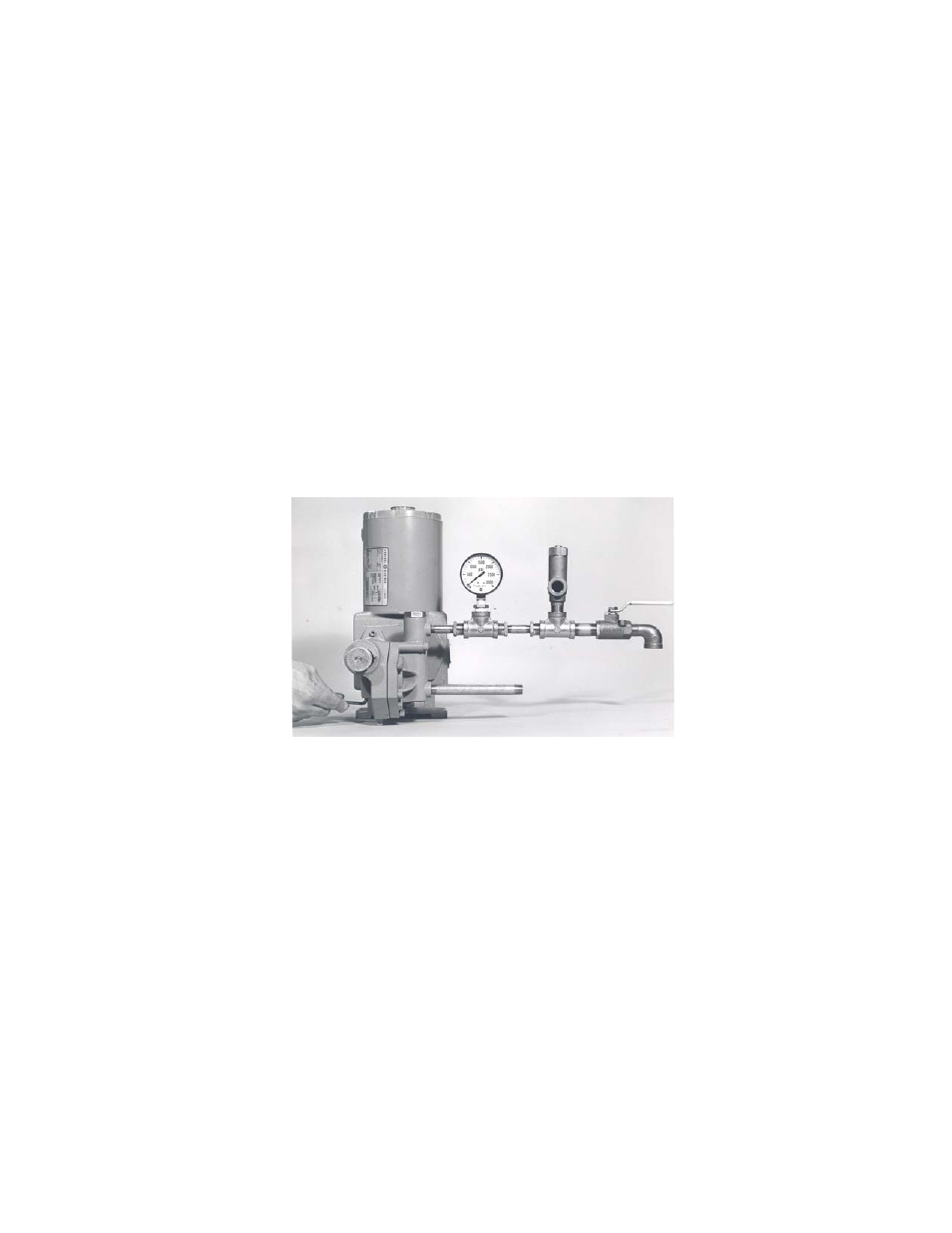
4.0.21 Connect a test set-up as shown in Figure IV below.
4.0.22 Start and run the pump until all air is relieved from the discharge liquid (hand valve open).
4.0.23 Remove Relief Valve Plug (Fig. #5651).
4.0.24 Close hand valve; pressure gauge should read 175 psi, depending on pump model.
4.0.25 Use the 1/4” Allen Wrench to adjust spring tension by turning Relief Valve Adjusting Screw
(FIG. #5652).
(1) To increase pressure, turn Relief Valve Adjusting Screw (Fig. #5652) in.
(2) To decrease pressure, turn Relief Valve Adjusting Screw (Fig.#5652) out.
4.0.26 After resetting or adjusting pressure, replace Relief Valve Plug (Fig. #5651).
CAUTION
Never turn Relief Valve Adjusting Screw (Fig. #5652) completely in.
Do not attempt to set the internal relief valve more than 200 psi in excess of name plate rating.
4.0.3
Parts required to test or adjust Relief Valve Pressure.
1 Pc.
1/2” x1/4” reducer bushing
1 Pc.
1/2” street elbow
3 Pcs.
1/2” pipe nipple 2” long
1 Pc.
1/2” hand valve
2 Pcs.
1/2” tee
1 Pc.
3/4” MNPT X 5/8” hose (fitting)
1 Pc.
5/8” hose, as required
1 Pc.
1/4” pressure gauge (minimum gauge pressure 500 psi)
1 Pc.
Allen wrench 1/4”
1 Pc.
External relief valve (optional)
NOTE
The above parts must have a working pressure rating above the required set pressure.
FIGURE IV