Vi. operation and adjustments, Startup precautions – Spencer Power Mizer Multistage Centrifugal Cast Blowers User Manual
Page 7
7
WARnInG: REPLACE THE COuPLInG GuARD BEFORE
RESTARTInG THE BLOWER.
8. Bearing Lubrication
Motor Bearings. Follow the motor manufacturer’s recom-
mendations. Some motors are equipped with sealed bearings
not intended for relubrication; these motors have no grease or
drain plugs.
Blower Bearings–Grease Lubricated. These bearings are
packed at the factory and do not need greasing prior to start-
up. If, however, the blower has been stored for three months
or longer, remove the bearing caps and check for moisture or
hard grease. Discard any hard or dry grease and relubricate if
necessary.
Blower Bearings–Oil Lubricated. The type and quantity of
oil are very important. Use only Mobil SHC626 synthetic oil or
one of these equivalents:
• Exxon TRESSTIC
®
SHP synthetic oil, ISO Grade 68
• Amoco Syntholube SL compressor oil, ISO Grade 68
• ROYCO
®
synthetic compressor fluid #468
• Royal Purple Synfilm Grade 68
CAuTIOn: Do not mix oils; thoroughly drain the bearing
sump and oiler before changing to a different brand of oil.
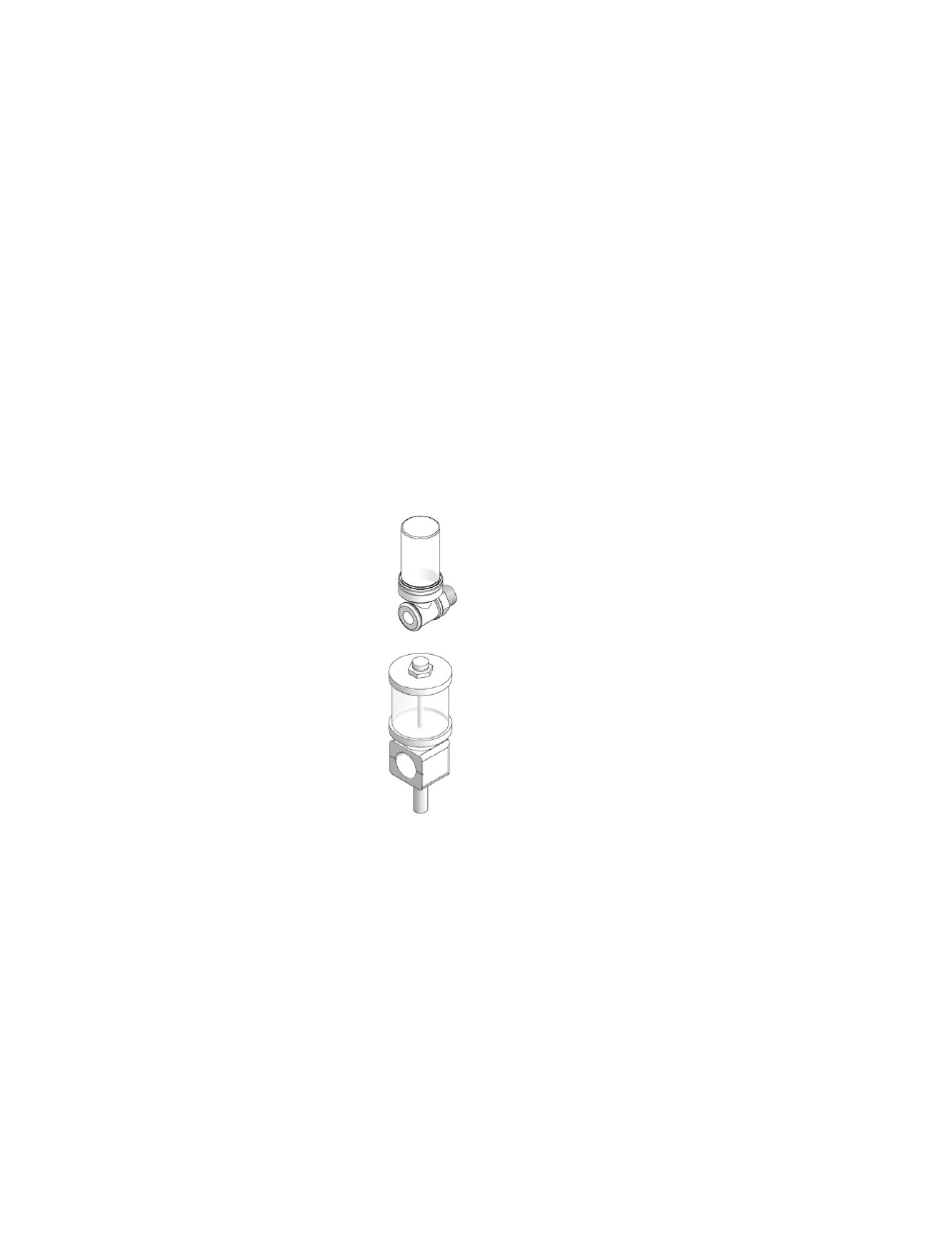
Constant Level Oilers
Some Spencer oil-lubricated blowers are
equipped with constant level oilers (one
each bearing housing). These maintain
an established oil level by replacing the
oil lost through seals, vents and various
components in the bearing housing and
sump. The oiler itself is replenished by
periodically refilling the reservoir (upper
portion of the oiler).
NOTE: Constant level oilers cannot
reduce oil levels that are too high.
Because maintenance of the correct oil
height is critically important, Spencer
constant level oilers incorporate a tubular
spout fitted with a view port and oil level
scribe line.
Use only approved lubricants.
See Section VII on Lubrication for verifying the correct oil
height.
9. Shaft Seals
Shaft seals at both the inlet and discharge ends minimize
leakage of gas into or out of the blower. Cast aluminum
labyrinth seals are standard; single and double carbon ring
seals are optional.
NOTE: Series 2500 and 3500 blowers intended for gas service
are equipped with an inlet end single carbon ring shaft seal
and a discharge end sealed bearing housing.
Blowers equipped with double carbon ring seals have purge
connections extending from each bearing housing which must
be connected to a supply of nitrogen or filtered shop air. The
supply should be regulated so the purge gas pressure at both
the inlet and discharge is approximately 0.5 PSI greater than
the process pressure.
NOTE: Blower inlet and discharge pressures are different,
therefore purge pressures at the inlet and discharge seals
should be established and regulated separately.
CAuTIOn: Do not operate double carbon ring seals with-
out a properly pressurized purge connection. This will
render the seal ineffective and could damage it.
10. Motor Rotation
A rotation arrow is located on the blower casing. “Bump” or
jog the start button and observe the direction of rotation of
the motor shaft. Rotation must be counterclockwise as viewed
from the discharge end. If the rotation is incorrect, the motor
wiring must be changed.
VI. Operation and
Adjustments
Startup Precautions
Before operating a new blower for the first time, review its
installation and setup to be sure that no steps have been
overlooked.
1. Installation Check List
• Is there any damage from transportation or installation,
especially to the oiler and oiler bracket?
• Is the machine level?
• Are the oilers level and is the oil height set correctly?
(Oil lubricated blowers only)
• Have all packing, shipping materials and tools been removed?
• Is the inlet filter in place?
• Are isolation pads in place?
• Is the piping connected and supported?
• Are flexible connectors in place between blower and piping?
• Are safety guards in place?
2. Adjustment Checks
• Are the oilers filled? (Oil lubricated blowers only)
• Is the coupling aligned within tolerances?
3. Operational Checks
• Is the throttling valve closed or properly positioned?
• Do the blower shaft and driver spin freely?
• Is the isolation valve (if any) open?
• Is the system ready for air or gas delivery?
• Has rotation been checked?
• Are motor and electrical accessories properly wired?
• Is the control panel energized?
• Have maintenance and operations personnel been notified?
CAuTIOn: This blower must have adequate system resist-
ance at all times to avoid operation at or near free delivery
(wide open). It is typically imposed by the process and
supplemented with a throttling valve. Running the blower
overloaded will damage the motor.