Infinity Drain WW 5 Series Installation Instructions User Manual
Page 5
5
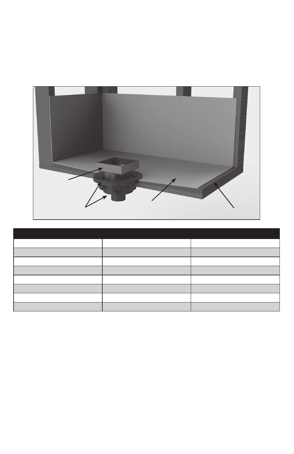
5. Using desired floor material, mark the
thickness of the material along the outside
of the throat (B), so that it will finish 1/16”
above the channel. Lay gravel or other porous
substrate over weep holes of the top clamp
down plate (C1). Spread a final mortar bed up
to the marked thickness, less the thickness of
thinset. Pitch this bed in all directions toward
the center drain. Once dry, apply a bead
of silicone caulk around the throat (B). Lay
thinset and finishing material. Have material
finish to the edge of the throat (B).
DO NOT
allow finishing material to finish on top of the
stainless steel channel edge.
5. Usando el material deseado, marque el
espesor del material a lo largo de la parte
afuera del cuello (B), para que termine
1/16” arriba del canal. Coloque grava u otro
sustrato poroso sobre los orificios de drenaje
(C1). Propagar un motero hasta el espesor
marcado, menos del espesor del thinset. Bree
esto en cuatro direcciones hacia el centro
drenaje. Una vez que este seco, aplique un
cordón de silicona alrededor de cuello (B).
Coloque thinset y material terminado al
borde superior del cuello (B).
NO PERMITA
que el material terminado termine enzima del
canal de acero inoxidable.
4. Reattach the top clamp down plate (C1)
to the clamp down drain body (C2) over the
waterproofing layer using bolts. Thread the
throat (B) of the drain into top clamp down
plate (C1). Adjust to the desired height. Turn
clockwise to lower, counter-clockwise to
raise. When determining desired height,
include thickness of mortar, thinset and
finishing material.
4. Vuelva a colocar la parte superior de la
placa (C1) al drenaje (C2) sobre la capa de
impermeabilización usando tornillos. Rosca
el cuello (B) del drenaje en la placa del
drenaje (C1). Ajústelo a la longitud deseada.
Gire hacia la derecha para bajar, hacia la
izquierda para aumentar. Al determinar
la altura deseada, incluía el espesor del
mortero, thinset y el material terminado.
(C) Clamp Down
Drain Assembly
Waterproofing
Membrane
Primary Motar Bed
(B) Throat
(C1)
(C2)
Model
Overall Minimum Height
Overall Maximum Height*
LTD 5
1 ⅛”
2 ¼”
RTD 15
¹³⁄
¹⁶
”
1 ⁷⁄
¹⁶
”
TD 15
1 ⁵⁄
¹⁶
”
2 ¹⁄
¹⁶
”
TD 20
1 ⁵⁄
¹⁶
”
2 ¹⁄
¹⁶
”
WW 5
¾”
1 ¾”
LW 5
⁷⁄
¹⁶
”
1 ⁷⁄
¹⁶
”
G-Series – T2
⅝”
1 ⅝”
G-Series – T4
⅝”
1 ⅝”