Rear panel features, Installation and operation, cont’d – Extron Electronics YCS SW2 A User Guide User Manual
Page 12
YCS SW2 A • Installation and Operation
Installation and Operation, cont’d
2-10
YCS SW2 A • Installation and Operation
2-11
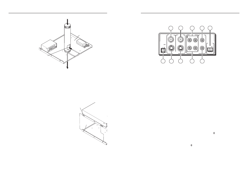
Rear Panel Features
1 2
VIDEO
VIDEO
AUDIO
S-VIDEO
CONTACT
AUTO-SW
POWER
12V
0.4A MAX
INPUTS
OUTPUT
1
1
INPUTS
OUTPUT
2
2
L
R
R
L
REMOTE
7
3
2
4
6
1
5
8
9
10
Figure 2-10 — YCS SW2 A rear panel
a
Input 1 connector — Connect a composite video input source to
this female BNC connector.
b
Video output connector
— Connect a composite video display
device to this female BNC connector.
c
Audio inputs 1 and 2 (left channel)
— Connect the left stereo
audio channel(s) of your input source(s) to one or both of these
white
female RCA connectors.
d
Audio output connector (left channel) — Connect the left
stereo audio channel of your output device to this white female
RCA connector.
e
Autoswitching and contact closure connector — This 3-pin,
3.5 mm captive screw connector can be used for autoswitching
or for control by contact closure.
•
To enable control by contact closure, connect an optional
contact closure device to pins 1, 2, and (ground). (See
“Contact closure,” later in this chapter.)
•
To enable autoswitching, short all three pins together (pin 1
to pin 2 and pin 2 to ). (See “Autoswitching,” later in this
chapter.)
f
Audio output connector (right channel) — Connect the right
stereo audio channel of your output device to this red female
RCA connector.
g
Audio inputs 1 and 2 (right channel)
— Connect the right
stereo audio channel(s) of your input source(s) to one or both of
these red female RCA connectors.
FRONT
REAR
Cable Input from
Sources (AV control)
Cable Access
Hole
Bottom Plate
Cable Output
to Projector
1
2
VID
EO
VID
EO
AU
DIO
S-VI
DE
O
CO
NT
AC
T
AU
TO
-SW
PO
WE
R
12V
0.4
A M
AX
INP
UT
S
OU
TPU
T
1
1
INP
UT
S
OU
TPU
T
2
2
L
R
R
L
RE
MO
TE
Figure 2-9 — Routing the cables for the PMK 450
7
.
Connect the cables to the YCS, its power supply, and
any additional devices/power supplies that you want to
mount.
8
.
Pull excess cable back into the ceiling. Feed the device(s)
output cables to the projector through the cable access hole
and out through the bottom of the pipe.
8.
Insert the lugs on the bottom
plate into the slots on the top
plate and slide the bottom plate
into position.
9
.
Lock the top and bottom plates
together with the security screws
10
. Pass the AC power cord through
the slot at the rear of the top
plate.
11
. Reattach the front and rear
plates.
Lugs (4)
Slots (4)