9 sw av series switchers • operation, Example 4: adjust the audio level – Extron Electronics SW AV Series User Guide User Manual
Page 29
3-9
SW AV Series Switchers • Operation
number of 1 dB steps you increment or decrement the audio level (see step 4),
you can determine the exact gain or attenuation setting.
The +dB LED on indicates a positive (gain) level. The -dB LED on indicates a
negative (attenuation) level. Both LEDs on indicate 0 dB.
4
.
Press and release the
and
buttons to increase and decrease the audio
level by 1 dB or press and hold the buttons to increase or decrease the level by
3 dB per second. The
and
LEDs flash to indicate each 1 dB level change.
Each time you press and release the
or
button, wait for the
or
LED to flash before pushing the button again. Pressing the button early may
not increment or decrement the audio level.
5
.
Press and hold the Audio Conf/Save button until the Audio Conf/Save LED
turns off to save the gain value in memory and exit the audio display and
adjustment mode.
1
.
There is one audio level setting per input. The setting is shared by the left
and right audio inputs.
2
.
The audio level settings are stored in non-volatile memory. When power
is removed and restored, the audio level settings are retained.
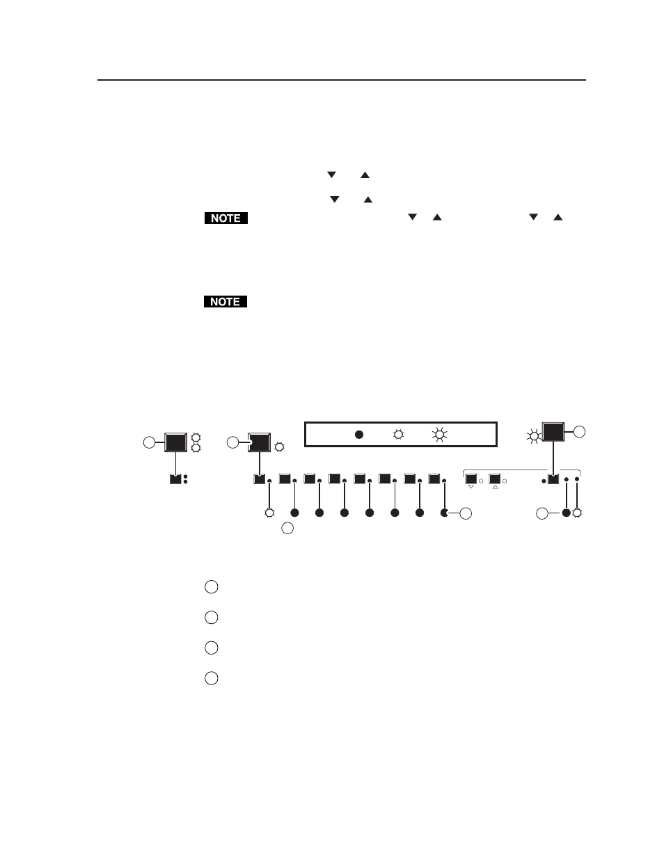
Example 4: Adjust the audio level
See figure 3-8 and figure 3-9 (on page 3-10) for an example in which the audio level
is adjusted.
8
7
6
5
4
3
2
1
AUDIO
CONF/SAVE
-dB
+dB
VIDEO
AUDIO
I/O
B
C
D
Indicates +6 dB to +11 dB range
CONF/SAVE
LED key: = off, = on, = blinking
B
B
D
D
Press
A
Press
Press
and hold
VIDEO
AUDIO
I/O
Figure 3-8 — Example 4: Viewing the audio level
A
(Video AND audio switchers) Press and release the I/O button as necessary
to select audio (or audio and video). The audio LED lights in either case.
B
Press and release an input button to select an input. The associated input
LED lights.
C
Press and hold the Audio Conf/Save button until the Audio Conf/Save LED
starts blinking.
D
The gain or attenuation value is displayed in the input 1 through 4 LEDs. In
figure 3-8, the LED readout shows a range of +6 dB to +11 dB.