Controls and indicators, Input selection controls and indicators, Operation – Extron Electronics SW RGBHV Series User Guide User Manual
Page 23: Operation, cont’d, Sw rgbhv series switchers • operation 3-2
Operation, cont’d
SW RGBHV Series Switchers • Operation
3-2
Operation
Controls and Indicators
The SW RGBHV family of switchers have 2, 4, or 6 input buttons and LEDs on the
front panel. Audio models also have front panel configuration controls and LEDs.
All models have an Auto/Manual mode selection switch on the rear panel.
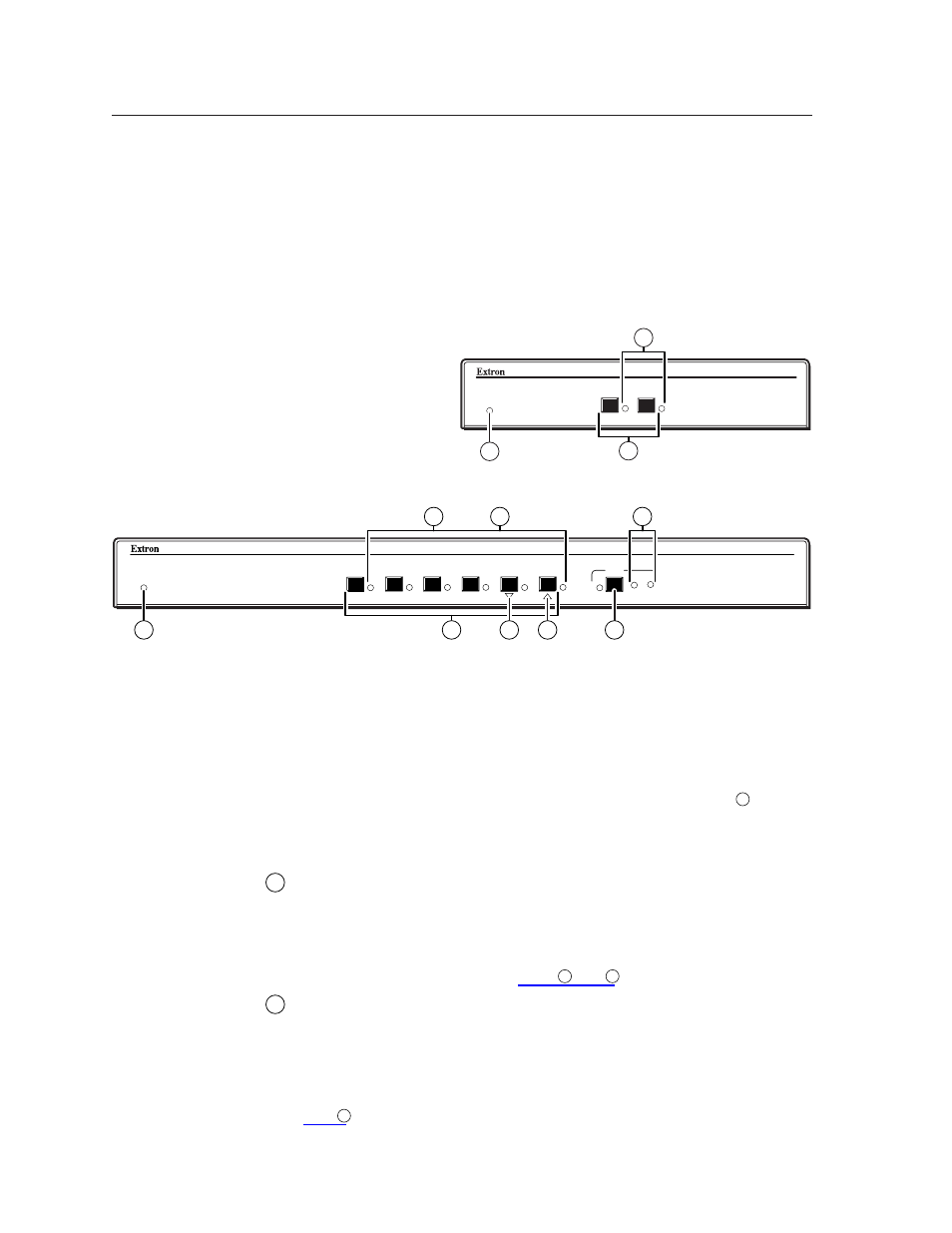
Figure 3-1 shows the front panel of an SW2 RGBHV switcher. Figure 3-2 shows the
front panel of an SW6 RGBHV A switcher. These two examples show all of the
combinations of buttons and enclosure sizes that you may encounter with your
particular switcher. Figure 3-3 shows the location of the Auto/Manual switch on
the rear panel.
SW2 RGBHV
RGBHV & AUDIO SWITCHER
AUTO SWITCH
ACTIVE
2
1
9
2
1
Figure 3-1 — SW2 RGBHV front panel
SW6 RGBHV A
RGBHV & AUDIO SWITCHER
AUDIO
CONF/SAVE
6
5
4
3
2
1
AUTO SWITCH
ACTIVE
-dB
+dB
9
6
3
7
2
1
4
5
Figure 3-2 — SW6 RGBHV A front panel
In the following descriptions, you will find the following terms:
•
Video-only switcher
— Switches RGB video only. No audio switching.
•
Analog audio switcher
— Switches analog audio on captive screw
connectors as well as RGB video.
On audio switchers, two of the input buttons and LEDs have dual functions.
Double function controls on figure 3-1 and figure 3-2 have two callouts (
n
numbers), each indexed to a function in the following pages.
Input selection controls and indicators
1
Input buttons —
When pressed, each input button selects the associated
input for output.
On some audio-switching models, the rightmost input buttons (Input 1 and
Input 2 on SW2 models and Input 5 and Input 6 on SW6 models) are also used
to decrease and increase the amount of audio gain for a selected input. See
“Audio controls and indicators”, items
.
2
Input LEDs —
When lit, the input LEDs identify the selected input. If audio
is broken away (available under RS-232 control only), the selected video input
is indicated by a steadily lit input LED, and the selected audio input is
indicated by a blinking input LED.
On the SW4 RGBHV A and SW6 RGBHV A, the input LEDs also indicate the
audio level of the selected input. See “Audio controls and indicators”,
item
.