Cabling and rear panel views, Inputs, 7 sw rgbhv series switchers • installation – Extron Electronics SW RGBHV Series User Guide User Manual
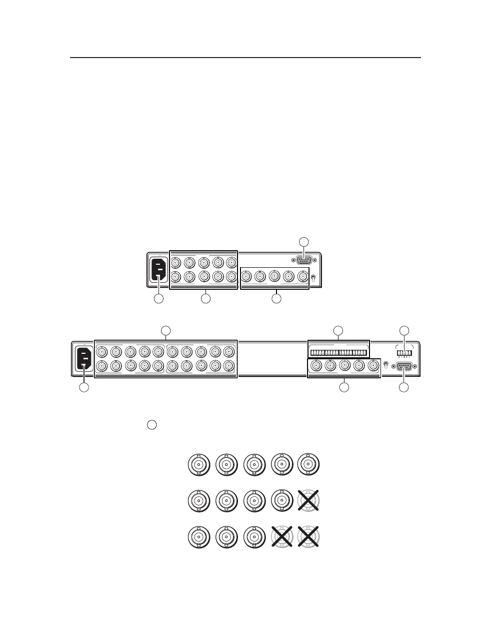
Page 18: Figure 2-5 — sw2 rgbhv video switcher, Figure 2-6 — sw4 rgbhv a switcher with audio, Figure 2-7 — video input and output connections
2-7
SW RGBHV Series Switchers • Installation
c
.
Tighten the screws.
d
.
Replace the switcher on the underside of the surface (step 6).
Cabling and Rear Panel Views
All connectors are on the rear panel. The switcher can be connected to up to six
RGBHV or component video devices and (audio models only) stereo audio devices,
depending on the model. The video and/or audio output output is identical to the
selected input; the switchers perform no sync or video format manipulation.
SW 2 models are in half-rack width enclosures and the rest of the models are in full-
rack width enclosures. Figure 2-5 shows an SW2 RGBHV video switcher.
Figure 2-6 shows an SW4 RGBHV A video and audio switcher. The two switchers
shown have all of the connector configurations that are available in the SW RGBHV
product family covered in this manual.
Switchers with video capabilities can switch video and audio separately (audio
breakaway).
AUTO
MANUAL
REMOTE
100-240V 1.3A
INPUT 1
INPUT 2
R
G
B
H/HV
V
50-60Hz
V
OUTPUT
R
G
B
H/HV
6
3
5
1
Figure 2-5 — SW2 RGBHV video switcher
100-240V 1.3A
50-60Hz
REMOTE
AUTO
MANUAL
INPUTS
L R
L R
3
4
OUTPUT
OUTPUT
V
R
G
B
H/
HV
2
1
L R
L R
L R
INPUT 1
INPUT 2
R G B
H/HV
V
INPUT 3
INPUT 4
R G B
H/HV
V
6
4
3
1
5
2
Figure 2-6 — SW4 RGBHV A switcher with audio
Inputs
1
RGB and component video inputs
— For each input, connect an RGBHV,
RGBS, RGsB, RsGsBs, or component video source to these BNC connectors.
Connect the cables as shown in figure 2-7.
G
RGBHV
RGBS
RGsB,
RsGsBs
Component
B
H
/HV
V
R
G
B
H/
HV
V
R
G
B
H/HV
V
Figure 2-7 — Video input and output connections