Installation, cont’d, Rear panel connectors and cabling, Caution – Extron Electronics Wallplates Installation User Manual
Page 7
Wallplates • Installation
Wallplates • Installation
Installation, cont’d
1-5
1-4
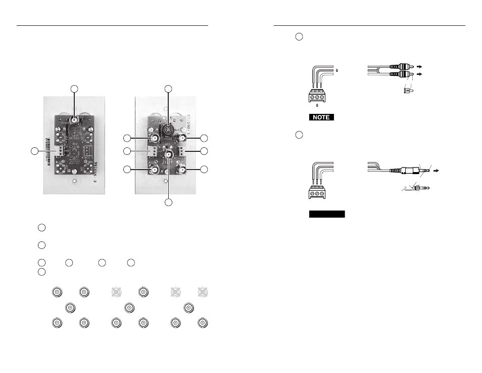
Rear Panel Connectors and Cabling
The WP wallplates share a similar circuit board design, which
means that each type of rear panel connector will be in the same
place on each model, but the quantity and selection of
connectors differs from model to model. The WP 120 and
WP 180 are shown here as examples, but the cabling and wiring
instructions apply to any wallplate with a particular connector.
8
RCA audio connector
— For unbalanced stereo audio that was
input via two front panel RCA connectors, insert wires directly
into this 3.5 mm direct insertion captive screw connector as
shown below, and tighten the screws to secure the wires.
RCA
Connector
L
R
Ground (Sleeve)
Left
Right
Left
Right
Tip-Sleeve Connectors
(RCA Jacks)
To audio device,
switcher, or
projector
Tip (Signal)
Sleeve (Gnd)
R
L
Follow the wiring diagram above. The printing on the
circuit board may or may not match the wiring pattern.
9
Mini 3.5 audio connector
— For unbalanced stereo audio that
was input via the front panel 3.5 mm mini stereo jack, insert wires
directly into this 3.5 mm direct insertion captive screw connector
as shown below, and tighten the screws to secure the wires.
Mini 3.5
Connector
Tip-Ring-Sleeve Connector
(Mini Stereo Jack)
T S R
Sleeve (Ground)
Tip (Left, +)
Ring (Right, -)
To audio device,
switcher, or
projector
Tip (+)
Sleeve (Gnd)
Tip (L, +)
Ring (R, -)
Sleeve (Gnd)
R
T
S
CAUTION
Connect the sleeve to ground (Gnd). Connecting the
sleeve to a negative (-) terminal may damage audio
circuits in the audio device, switcher, or projector.
1
Composite video (Video) connector
— Connect a coaxial cable
to this female BNC connector.
2
S-video (SVideo) connector
— Connect an S-video cable to this
4-pin mini DIN connector.
3
= Red,
4
= Green,
5
= Blue,
6
= horizontal sync (H),
7
= vertical sync (V)
— Connect coaxial cables to these female BNC
connectors for the appropriate RGB signal format.
RED
BLU
H
V
GRN
V
RED
BLU
H
V
GRN
RED
BLU
H
GRN
RGBHV
RGBS
RGsB, RsGsBs
1
3
8
8
9
5
4
7
6
2
WP 120
Rear
WP 180
Rear