Rear panel, Installation and operation, cont’d, Figure 2-4 — sw8 vga ars rear panel – Extron Electronics SW8_12 VGA Ars User Guide User Manual
Page 15: Figure 2-5 — sw12 vga ars rear panel
Installation and Operation, cont’d
SW8/12 VGA Ars • Installation and Operation
2-6
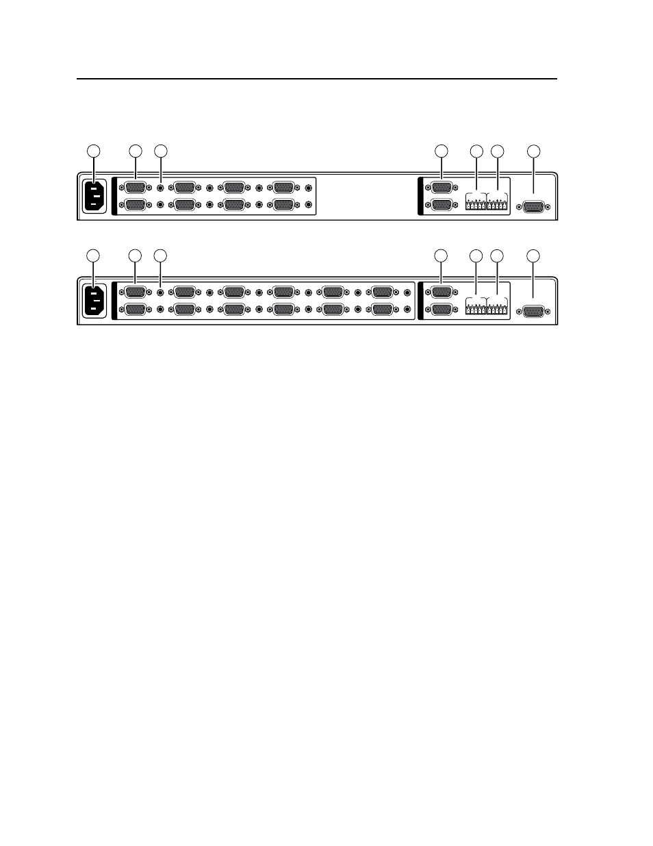
Rear Panel
The SW8/12 VGA Ars switcher rear panel connectors are described below.
RS-232
100-240V 50/60Hz
1.2A MAX
1
2
SW8 VGA Ars
3
4
5
6
7
8
1
2
FIXED
VARIABLE
L
R
L
R
I
N
P
U
T
S
O
U
T
P
U
T
S
5
6
7
4
1
2
3
Figure 2-4 — SW8 VGA Ars rear panel
RS-232
100-240V 50/60Hz
1.2A MAX
1
2
SW12 VGA Ars
3
4
5
6
7
8
9
10
11
12
1
2
FIXED
VARIABLE
L
R
L
R
I
N
P
U
T
S
O
U
T
P
U
T
S
5
6
7
4
1
2
3
Figure 2-5 — SW12 VGA Ars rear panel
a
AC power receptacle — Plug a standard IEC power cord into this receptacle
to connect the switcher to a 120/240 VAC, 50/60 Hz power source.
b
Computer video input connectors — 8 or 12 15-pin HD female connectors.
Connect computer video inputs (VGA, SVGA, XGA, SXGA, WXGA, SXGA+,
UXGA, QXGA, or HDTV).
c
Audio input connectors — Eight or twelve 3.5mm TRS jacks. Connect
unbalanced audio inputs.
d
Video output connectors — Two 15-pin HD female connectors deliver
simultaneous buffered video output.
e
Fixed audio output connector — One 3.5mm 5-pole captive screw connector
delivers a fixed volume stereo balanced/unbalanced audio output.
f
Variable audio output connector — One 3.5mm 5-pole captive screw
connector delivers a variablevolume stereo balanced/unbalanced audio
output. Volume is variable via the RS-232 control port. The volume
adjustment range is 0 (-84 dB) through 100 (0 db). The default volume setting
is 100 (0 dB).
g
RS-232 Control port — A 9-pin D female connector for serial connection to a
PC or controller.