Installation, Interface details, Ul requirements – Extron Electronics RGB 472xi_474xi_478xi_478 Mxi User Guide User Manual
Page 8: Front panel features and cabling, Rgb 470 xi xi xi xi xi series • operation
RGB 470xi
xi
xi
xi
xi Series • Operation
Installation
RGB 470xi
xi
xi
xi
xi Series • Operation
2-3
Interface Details
Front panel features and cabling
UL Requirements
The following Underwriters Laboratories (UL) requirements
pertain to the installation of the RGB 470xi series of interfaces
into a wall or furniture.
1.
These units are not to be connected to a centralized DC
power source or used beyond their rated voltage range.
2.
These units must be installed in UL listed junction boxes.
3.
These units must be installed with conduit in accordance
with the National Electrical Code.
2-2
H. SHIFT
INPUT
SELECT
MIN/MAX
AUDIO 1
AUDIO 2
WITH ADSP™
RGB 478xi
INPUT 1
FOLLOWS
MONITOR
MONITOR
INPUT 2
INPUT 1
1
2
1
2
3
9
8
4
5
7
14
6
S-VIDEO
VIDEO
L/MONO
AUDIO
R
MIN/MAX
WITH ADSP™
RGB 474xi
MONITOR
INPUT 2
INPUT 1
H. SHIFT
INPUT
SELECT
1
2
AUDIO 1
AUDIO 2
INPUT 1
FOLLOWS
MONITOR
CAT6
1
2
3
9
8
4
5
7
10
11
CAT6
6
12
13
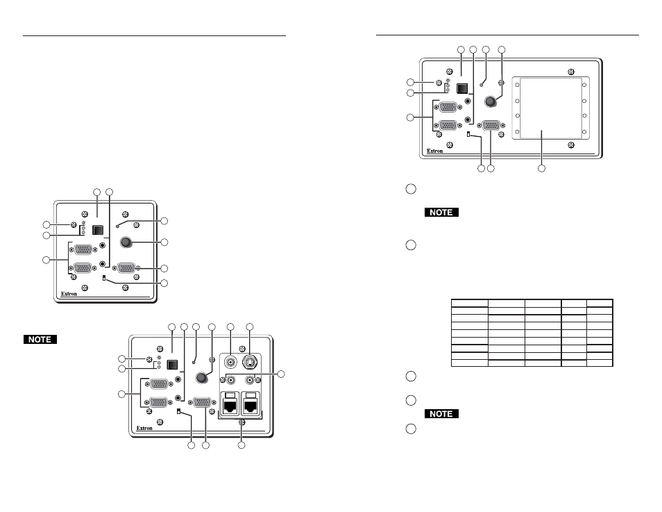
The
RGB 478 Mxi
(not pictured) is
functionally
identical to the
RGB 478xi
below, except it
fits in a 3-gang
box and accepts
four mini AAPs
(MAAPs).
1
Faceplate screws
— These screws secure the faceplate to the rest
of the interface.
Do not remove these faceplate screws while the interface
is attached to the wall or the detached interface may fall
down inside the wall.
2
Power/signal LED
(Inputs 1 and 2) — These LEDs light
•
red (initially) to indicate that the interface is receiving power.
•
as indicated by the table below, if an active sync signal is
present at the input indicated, and the interface is receiving
power.
3
Video input connectors (1 and 2)
— Plug a male 15-pin HD
connector from the video source into one of these two connectors.
4
Input select switch
— Use this switch to an select the input signal.
Autoswitch setting of the dip switch disables this control.
5
Audio input connectors
(1 and 2) — Plug a 3.5 mm plug into
one of these jacks for unbalanced audio input. Wire the male
plug as shown on the next page.
Input Selected
Input 1
Input 2
Input 1
Input 2
Input 1
Input 2
Input 1
Input 2
Input 1 Signal
Not Present
Not Present
Present
Present
Not Present
Not Present
Present
Present
LED 1
Red
Off
Green
Amber
Red
Off
Green
Amber
Input 2 Signal
Not Present
Not Present
Present
Present
Not Present
Not Present
Present
Present
LED 2
Red
Off
Green
Amber
Red
Off
Green
Amber
H. SHIFT
INPUT
SELECT
MIN/MAX
AUDIO 1
AUDIO 2
WITH ADSP™
RGB 472xi
INPUT 1
FOLLOWS
MONITOR
MONITOR
INPUT 2
INPUT 1
1
2
4
6
7
8
5
9
1
2
3